|
October 1932 Radio-Craft
 [Table
of Contents] [Table
of Contents]
Wax nostalgic about and learn from the history of early electronics.
See articles from Radio-Craft,
published 1929 - 1953. All copyrights are hereby acknowledged.
|
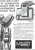
Mallory-Elkon "Elkonode" B-battery eliminator.
What the heck is an Elkonode? That was my response to its mention in this Radio
Service Data Sheet for the Galvin Motorola Model 61 Automotive Receiver. The Mallory-Elkon
Elkonode was an electromechanical vibrator device for DC-DC conversion. An oscillating
circuit opened and closed a set of contacts being fed with the automobile's DC supply,
thereby creating a chopped waveform which was applied to a step-up transformer,
then rectified and filtered to provide the high plate voltage for the radio's vacuum
tubes. A Google search turned up a datasheet on the Mallory Elkonode. Per the info,
"The series 60, 70, and 80 Mallory Elkonodes (scroll down a couple screens) are described
as single-reed, full-wave inverters, with self-contained synchronous rectifiers.
These units within themselves supply direct current, high voltage for radio receiver
plate supply. No tube rectifiers are required with these types." This 1932 Radio−Craft
magazine article recommends against attempting self-repair of Elkonodes (aka interrupters),
so restoration buffs will appreciate the instructions offered in the
datasheet (I had
Archive.org save a copy).
Galvin Motorola Model 61 Automotive Receiver
Radio Service
Data Sheet
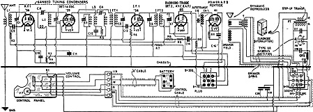 Incorporating a type 85 duodiode-triode
tube as a combination second-detector, automatic volume control and first A.F. amplifier.) Incorporating a type 85 duodiode-triode
tube as a combination second-detector, automatic volume control and first A.F. amplifier.)
This automotive receiver incorporates the following tube combination: Tube V1,
type '36 screen-grid as an R.F. amplifier; V2, type '39 variable-mu R.F. pentode
as a combination oscillator and first-detector; V3, type '36 screen-grid I.F. amplifier;
V4, type 85 duodiode-triode as a combination second-detector, automatic volume control
and A.F. amplifier; V5, type 41 high-mu special automotive pentode second A.F.
High voltages are obtained from the storage battery of the car by means of an
interrupter system and step-up transformer, in the manner described in the Sept.
1932 issue of Radio-Craft, pg. 152.
Following are the values of the components of this modern radio set: Condensers
C1, C2, C3, tuning condenser gang; C4, C8, coupling condensers; C5, C6, C7, I.F.
trimmers; C9, C13, C17 (buffer), .05-mf.; C10, 0.5-mf.; C-11, 0.25-mf.; C12, 500
mmf.; C14, .002-mf.; C15, .01-mf.; C16, 1. mf.; C18, C19, 8 mf.; C20, C21, 0.1-mf.
Resistor R1, volume control potentiometer, 0.5-meg.; R2, R4, R7, R8, 0.1-meg.;
R3, 75,000 ohms; R5, 5,000 ohms; R6, 500 ohms; R9, 0.2-meg.; R10, 50,000 ohms; R11,
0.7-meg.
It is not recommended that any repairs be made to a defective Elkonode (interrupter.)
All such units should be returned to the factory (Galvin Mfg. Corp., Chicago, Ill.),
or to the manufacturers of the Elkonode (see label on unit).
An open buffer condenser, C17, will be indicated by failure of the rectifier
tube V6 to stay ionized. A purple glow in the tube is an indication of correct operation
of this type of rectifier; a shorted C17 condenser will be indicated by spasmodic
operation of the Elkonode, as well as failure of V6 to glow. As a general rule,
when spasmodic operation of the Elkonode is observed it is an indication that the
Elkonode is not feeding in to the correct load; it either is underloaded or overloaded;
two undesirable conditions.
After the Elkonode has been removed, it may be tested by applying 6 volts to
the large terminals, with positive polarity to the brown wire; it is also necessary
to connect a 5,000-ohm resistor across the red (or green) and black wires, together
with an 8 mf. electrolytic condenser and a voltmeter. With this setup, the Elkonode
should consume not more than 2.25 A.; the voltage drop across the 5,000-ohm load
should he between 160 and 170 volts, provided the battery voltage is exactly 6.3.
The following precautions should be observed: Do not remove the receiver section
of the set from the power pack, with the set turned on; the BR tube, V6, should
not be removed from its socket unless the set is turned off. Since the "A" supply
is polarized, it is necessary to make certain that the red wire connects to the
positive terminal and the white wire to the negative terminal of the battery; do
not operate the set with the "A" leads reversed, otherwise the Elkonode will be
damaged beyond repair. For this reason, the polarity of the car battery should be
double-checked by means of a voltmeter before the set is put into operation. (Reversed
connection to the "A" battery will be indicated by low "B" voltage, spasmodic operation
of the Elkonode and erratic flashing of V6.)
An ideal place for the reproducer is face-out, with the reproducer flush with
the instrument board, but such a position is undesirable because of the space factor.
Therefore, the first alternative is to leave it at the same level but to move it
back to the bulk-head, for good operation.
If there is not room to mount the reproducer in that position, a second method
is to face the reproducer toward the floorboards, with the front-edge of the reproducer
against the instrument board and the side against the side of the car, a position
available in most cars.
It generally necessitates two holes being drilled through the instrument board
to hold the reproducer and an additional bracket run from the adjacent side of the
reproducer to the side of the car. This location is rather new to some installation
men, but its acoustic properties are superior because of the additional baffle effect
which results from the close proximity to the instrument board.
Following is a listing of the preferred location for automotive radio receivers
to be used in the 1931 car models specified:
Ford, Model A: Motor compartment on the left side;
Chevrolet: Motor compartment on the left side or below the cowl on the right
inside; (For 1932 model, remove carburetor and air cleaner, temporarily.);
Buick: Below the cowl on the right inside;
Chrysler: Right side of car under cowl;
Pontiac: Left side of motor compartment or right side of car under cowl;
DeSoto: Ditto;
Plymouth: Left motor compartment or right side of car, under cowl;
Cadillac: Ditto;
Lincoln: Center of motor compartment or right side of car, under cowl;
Packard: Ditto; (Light Eight, left side of motor compartment.);
Oakland, V8: Below cowl on right side or right side of car, under cowl;
Studebaker: Left motor compartment or right side of car, under cowl;
Oldsmobile: Right motor compartment or right side of car, under cowl;
Auburn: Right motor compartment or right side of car, under cowl.
(The "bulkhead" is the partition in the car which separates the motor compartment
from the driver's compartment.)
Car manufacturers have furnished the following data regarding their provisions,
in 1932 models, concerning automotive radio antennas:
Chrysler: Roof antenna with lead-in and provisions for "B" battery box;
Dodge: Ditto;
DeSoto: Ditto;
Plymouth: Ditto;
Reo: Equipped with roof antenna and lead-in;
Rockne: Ditto;
Studebaker: Ditto;
Buick: All models, $6.00 additional for antenna installation;
Franklin: Roof antenna but no lead-in;
Ford: Ditto;
Cunningham: All models, additional charge for antenna installation.
Check the proposed antenna for ground by means of a 0-200 V. meter, of 1,000
ohms-per-volt type, and a 200 V. battery. Even on damp days the leakage should not
exceed 2 V. Lack of peak resonance on the antenna trimmer indicates a leaky antenna,
or one having too great capacity; in general, an antenna screen area of about 9
sq. ft. will be satisfactory.
The dynamic reproducer may be checked for a rubbing voice coil by applying 50
V., 60 cycles. to the two outside or "B" terminals of the output transformer; instead
of a clear, steady hum, a rubbing noise will be heard, if the voice coil is not
floating entirely clear.
Posted March 23, 2023
(updated from original post
on 1/9/2015)
Radio Service Data Sheets
These schematics, tuning instructions, and other data are reproduced from my
collection of vintage radio and electronics magazines. As back in the era, similar
schematic and service info was available for purchase from sources such as
SAMS Photofacts, but these printings
were a no-cost bonus for readers. There are 227 Radio Service Data Sheets as of
December 28, 2020.
-
AMRAD
Model 81 "Bel Canto"
-
GE
Model 250 Radio Service Data Sheet
- Hoffman
Model A300
- Emerson
Model 505
- Olympic
Models 6-501, 6-502, 6-503
- Radiola
Models 61-5, 61-10
- Farnsworth
Models ET-060, ET-061, ET-063
- General
Electric Model 321
-
Garod Model 6AU-1
- Truetone
Model D4620
- Westinghouse
Model H-148
- Wards Models
54BR-1501A, 1502A
- Majestic
Models 8S452, 8S473
- RCA Models
Q22A, Q32
- Zenith Model
5G003ZZ
- Mantola Models
92503 and 92504
- Emerson Model
508 Series 8-7434351 and Up
- Belmont Model
A-5D118
- Wards Model
74BR-2707A
- Crosley Model
56TP-L
- Admiral Model
7C60 Chassis 6B1
- 336
Belmont Radio Model 6D111, Series A
-
333 General Electric Models 100, 101, 103 and 105
- RCA Victor
Models 54B1, 54B-N, 54B2, 54B3 Radio Data Sheet 335
-
National Union "Presentation" Radio Model G-619
-
Zenith Radio Models 8H032, 8H033, 8H050, 8H052, 8H061
-
General Electric Farm Radio Model 280
-
Admiral Model 6RT44-7B1
-
Montgomery Ward Airline Model 04BR-1105A Radio
- Belmont
Model 678 Auto-Radio Set
- Sentinel
Model 217-P Portable Radio Set Radio
- Remler
Model No. 36 Dual-Wave Auto-Radio
-
Stromberg-Carlson No. 82 All-Wave Receiver
-
Majestic A.V.C. Model 290 Chassis
- FADA 9 Tube
Model 190 "Metal" All-Wave
- RCA Victor
Models 9T and K2 9-Tube, 5- to 566-Meter
-
Motorola "Golden Voice" Model
-
RCA Victor Model H-6
-
Simplex Model TA
-
Automatic "Magic Eye" Model A1
- Silvertone
Models 4488 and 4588 (Chassis No.101412) and 4488A and 4588A (Chassis No. 101412A)
- RCA Victor
Model M109 "De Luxe" 7-Tube Auto-Radio Receiver
- Crosley Model
6625 6-Tube 3-Band Receiver
- International
Model 77 Series 7-Tube Dual-Band Receiver
- Belmont
Model 6D121
-
General Electric Models 60, 62
- Admiral
Model 7C64
-
Radiola "28" Super and "104" Power Speaker
- Sonora
Model TW-49
-
Stromberg-Carlson Models 1020, 1120, Series 10
- Air King
Model 4604D
- Sparton Models
526, 526X, 526PS
- Truetone
Model D2624
- Admiral
Models 6EI, 6EIN
- Detrola Models
571A, 571B
-
General Electric Model 250
- Howard Model
920
- Colonial
Model 652 5-Tube Broadcast-Short-Wave
-
Fairbanks-Morse
9-Tube All-Wave Model 91
-
International Model 500 5-Tube Dual-Range Battery
- Emerson Model
678 "Auto-Dynamic" 5 Tube
-
Stromberg-Carlson
Nos. 230 and 231 Series
- Atwater
Kent Model 649 All-Wave
-
Howard Model G-26, and "Airplane 4" Model AA25
-
Montgomery Ward "Airline" Series 7GM 7-Tube High-Fidelity Receiver
- RCA
Victor Model T5-2 5-Tube, 2-Band A.C. Superheterodyne Receiver
-
Majestic
"Models 50," "51" and "52"
-
Bremer-Tully Model 7-70 and 7-71
-
General
Electric Model M-49 4-Tube Radio-Phonograph Dual-Wave Superheterodyne
- RCA-Victor
Radiola "Superette" Model R7 Superheterodyne
- Crosley Model AC-7
and AC-7C
-
Westinghouse
"Columnaire" Models WR-8 and WR-8-R (Remote Control)
-
Characteristics
of Metal Tubes - and Other "Octal" (8-Prong) Base Types
- Kolster K20,
K22, K25, K27 and K37 Six-Tube Receivers
-
Stromberg-Carlson
Nos. 62 and 63, 8-Tube High-Fidelity Chassis
- RCA Model
103, 4-Tube A.C. Compact Dual-Wave
- FADA "Special"
Model 265-A and FADA "7" Model 475-A
-
General Electric Model C-62 6-Tube Battery
- Emerson
5A Automotive
- Zenith
666 Automotive
- Motorola
100 Automotive
-
Crosley
Roamio 4-A-1 Automotive
-
American-Bosch
524A Automotive
- Crosley
Model 1316 (in Model 167 Console)
- RCA Victor
"High-Fidelity Electrola," Model R-99
- AMRAD
Model 81 ("Bel Canto" Series) Receiver
-
Fada 103 Fadalette, Stewart-Warner Series 108, DeWald 54 Dynette Sets
- RCA
Victor R-27 and Philco 53 Ultra-Midget A.C.-D.C. Radio Receivers
-
Majestic Models Fairfax and Sheffield 8-Tube
- Stromberg-Carlson
No. 29, 9-Tube Superhet
-
International Kadette Model 400 4-Tube Battery-Operated Superhet
- RCA Victor
Model 5M 5-Tube Auto Superhet
-
Majestic Model 11 Short-Wave Converter
-
Silver-Marshall
Model 727-DC Battery-Operated Superheterodyne
- RCA
Victor Model VHR-307 Home Recording - Phono-Radio Combination
-
Delco 32-Volt Radio Receiver Chassis Models RA-3, RB-3 and RC-3
- Majestic
Chassis Models 380 A.C. T.R.F., and 400 A.C.-D.C. Superheterodyne
- General
Motors S1A, S1B
- Admiral
Model 7C63, Chassis 7C1
- Westinghouse
Model H-133
- Arvin
Models 150TC, 151TC
- Kadette Model
90 Duplex
-
RCA-Victor "Magic Brain" Model 281
- Grunow
11A Chassis 11-Tube All-Wave Superheterodyne
-
Sears, Roebuck & Co., Silvertone "Rocket" Models 6110 and 6111
-
General Electric Model GD-52
-
Zenith Models 6D302, 6D311, 6D326, 6D336, 6D360
-
Allied Radio, Knight Model E10913
- Arvin Model
140P
- Emerson
Models 501, 502, 504
- Crosley
Model 56TD-W
- Hoffman
Model A500
-
Stewart-Warner
Model 9003-B
-
Zenith Models 6D014, 6D029
- Coronet
Model C-2
- Sparton
Models 7-46, 7-46PA, 8-46, 8-46PA
-
Stewart-Warner Models 9001-C, D, E, F
-
Zenith Models 5D011-5D027
- Bendix Models
636A, C, D
- ECA Model 108
-
International Model 66 and 666, 6-Tube Superhet
-
Ford-Philco
Radio, Model FT9, 6-Tube Auto-Radio Receiver
- Howard
Explorer Model W Deluxe 19 Tube All-Wave Superhet
- RCA Victor
Portable Table Electrola Model R-95
- Atwater
Kent Model 305Z 5-Tube 32 V. D.C. Superhet
- Kadette
Jewel Model 40 Chassis 3-Tube Ultra-Midget Receivers
-
General Electric Model N-60 6-Tube Auto Superheterodyne
-
Sparton Model 40 6-Tube T.R.F. Automotive Receiver
-
Clarion "Replacement" Chassis, Model AC-160 A.V.C. Superheterodyne
- Emerson Models
20A and 25A
- General
Electric K-40A
- Pilot Model
B-2
- RCA-Victor
Radiola Model M-30 Automotive Radio
- Motovox
Models 10A All-Electric and 10E Battery-Operated "Moto-Tetradynes"
-
Kennedy Superheterodyne Short-Wave Converter
- RCA
Victor Model R-78 B1-Acoustic 12-Tube
- Philco
Model 15 Series, 11-Tube Superheterodyne Chassis
-
Zenith Challenger Model 740
-
Sparton
Selectronne Receivers Models 1068 and 1068X
- Fada Model
155 Super Fadalette A.C.-D.C. Set
-
Clarion De Luxe Models AC-280 and 25-280
-
Crosley Model A-157 (River Roamio) Auto Radio
- Philco Model
'37-116 Codes 121 (Shadometer) and 122 (Dial Tuning)
-
Arvin Model 28
-
Philco Model 818
-
Fada Model 266 Motoset
-
Bosch Models 736, 737, 738
- RCA-Victor
Model 15U, Radio-Phonograph
- Sparton
Models 566 ("Bluebird" Mirror), A.C.-D.C. 5-Tube 2-Band Midget Superhet
- Atwater
Kent Model 776 6-Tube Auto Radio
- Stromberg-Carlson
No. 61 4-Band 7-Tube A.C.-D.C. Receiver
- Arvin Model
182TFM
- Crosley
Model 58TK
- Westinghouse
Model H-165
-
General Electric Models G-105 and G-106
- Silvertone
"F," "FF," "G," "H," and "J"
-
Stewart-Warner Model 03-5A1 to 03-5A9 (Chassis 03-5A) Senior Varsity Radio
- Radiola Models
61-6, 61-7
-
Westinghouse
Models H-104, H-105, H-107, H-108
- Farnsworth
Models EC-260, EK-262, EK-263, EK-264, EK-265
-
United
Models 980744, 980745
-
Stewart-Warner (R-127 Chassis) Models 1271 to 1279 All-Wave
- ERLA Model
4500 Dual-Wave T.R.F. 4-Tube A.C. Receiver
- Clarion No. TC-31
5-Tube A.C.-D.C. Superhet.
- Detrola Model
105C 5-Tube Dual-Band A.C.-D.C.
- Zenith
6-Tube All-Wave Chassis No. 5634
- RCA Victor
Model 261, 555 to 107 Meter
- Philco
Model 38-116; Code 125
-
Stewart-Warner "Ferrodyne" Chassis Model R-136
-
American-Bosch
Model 43OT 5-Tube 3-Band Superheterodyne
- RCA
Victor Model C9-4 9-Tube 3-Band Superheterodyne
- Kennedy "Model
826B" Combination Receiver
- Steinite
50-A and 102-A
- Pilot Model
63 All-Wave 6-Tube Superheterodyne
- Stromberg-Carlson
No. 69 4-Tube All-Wave Superhet. Selector (Converter)
- RCA
Victor Model 102 4-Tube A.C.-D.C. T.R.F. Receiver
- Bosch Models 60
and 61
-
Atwater Kent Models 30, 33, 35, 48 and 49
- Crosley Model
120 Senior Superheterodyne (Pliodynatron) Chassis
-
Columbia Screen-Grid 8 Receiver
-
General Electric Models A82 and A87, 8-Metal-Tube All-Wave A.C. Superhet.
- Colonial
31 and 32 D.C.
- Zenith 5-Tube
Triple-Wave Chassis nos. 5508 and 5509
- Remler Model
46 ("Scottie")
- General
Electric FA-60 and FA-61
-
Stewart-Warner
Series 900
-
Howard
Model B-5 (715), Series 1 and 2 (Sheaffer Radio-Clock-Pen Desk Set)
-
Ford-Philco Car-Radio Models F-1440 and F-1442
-
Brunswick Model 31 Combination Radio and Panatrope
- Emerson Models
38, 42 and 49, 6-Tube Dual-Wave (Chassis U6)
-
General Motors Chevrolet No. 601574 Automotive
-
RCA Victor M-104 (and M-108) Automotive
- Arvin-Ford
17-A Automotive
-
Westinghouse Model WR 207 & WR 208 5-Tube Dual-Band Superheterodyne
- Radiolas
"Super VIII" (AR-810, "Semi-Portable" (AR-812), 24 and 26
- Howard Model
45 A. V. C.
- Majestic
Model 25
-
Galvin Motorola Model 61
-
Arvin Model 6
- Admiral
Models 7T06, 7T12
- Garod Model 5A1
- Hoffman Model A301
-
Knight Model E10716 Battery Portable
- Arvin Models 555,
555A, 552N, 552AN
- Grantline Models
605, 606
- Truetone Model
D2616
- Belmont Model
5D128
- Arvin Models 444,
444A
-
International Kadette Model 1019
-
Stewart-Warner Models 97-561 to 97-569
- General
Electric Model 280
- Zenith Models 5R080,
5R086
- Truetone Models
D1747, D1748
-
Crosley Roamio Automotive T.R.F. Models 90, 91, 92
-
Crosley Roamio Automotive Superheterodyne Models 95, 96
-
Wells-Gardner Series 062
-
Emerson
Model AZ-196
- Belmont Model
5P19
- Crosley
Fortyfive
- Crosley Model
56FC
-
Emerson
Models 507, 509, 518, 522, 535
- Garod Model 6AU-1
- General
Electric Models 219, 202, 221
-
Crosley "Chairside" Model 567
-
Belmont Model 408 Battery "Farm"
- Wards Model
74BR-1055A
- Farnsworth
Models EK-081, EK-082, EK-083, EK-681
- Philco
Model 200-X Radio
-
Admiral "Aeroscope" Models 161-5L, 162-5L and 163-5L
- Philco
Model 59, 4-Tube A.C. Midget Superheterodyne
- Zenith
Farm Model 6V 27, 6-Tube Superhet
- Ward 10-Tube
All-Wave High-Fidelity Superhet, Series ODM
-
Philco-Packard
Deluxe
-
Canadian
Westinghouse Model 175
- Crosley Model
1155
- Philco Models
39 and 39A
-
Arvin Model 35 8-Tube Car-Radio
- Hetro
Air-Ace Series M
- Westinghouse
Models H-161, H-168, H-168A
- Garod Model 5A4
- Arvin Models 152T,
153T
- Belmont Model 5240
- Mantola Models 92505,
92506
- General Electric
Models 102, 102W, 107, 107W, 114, 114W, 115, 115W
- Crosley Model
555 (A.F.M.)
- Crosley Model
515 (Fiver)
- Crosley Model
425 (Travo)
-
Firestone-Stewart-Warner Model R1332
- Fairbanks-Morse
Model 81 "Farm" Set
- Clarion Model
423, 470, 471, 472, 480
-
International Radio Corp. Model 90
- Belmont Model
578 Series A
|