February 1930 Radio-Craft
Table of Contents ]
Wax nostalgic about and learn from the history of early electronics.
See articles from Radio-Craft,
The
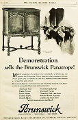
Brunswick Model 31 Combination Radio Panatrope was billed as the world's first all-electric
phonograph (as opposed to the mechanical crank-up models), combined with an AM radio.
It was designed with the assistance of RCA, many of whose components were integrated
into the unit. A video of a restored Panatrope is embedded on the page below the
data sheet. I couldn't find an official etymology for "panatrope," but the prefix
"pan" means "all-inclusive," and "trope" means "turning," like the turning of a
phrase. However, given that the Panatrope is a "turn"table, perhaps that was an
intentional distortion of the meaning to fit the device which it named, ergo, a
record player that had all available functions. That's my best shot at it. This Radio
Service Data Sheet for the Brunswick Model 31 Combination Radio and Panatrope appeared
in the February 1930 issue of Radio-Craft magazine. It includes
schematics and very detailed alignment instructions. A video of one in operation
is embedded below.
Brunswick Model 31 Combination Radio and Panatrope Radio
Service Data Sheet
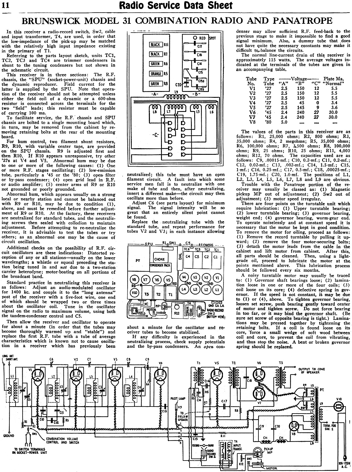
In this receiver a radio-record switch, Sw2, cable and input transformer, T4,
are used, in order that the low-impedance of the pick-up may be matched with the
relatively high input impedance existing in the primary of T1.
Referring to the parts layout sketch, units TC1, TC2, TC3 and TC4 are trimmer
condensers in shunt to the tuning condensers but not shown in the schematic circuit.
This receiver is in three sections: The R.F. chassis, the "SPU" (socket-power-unit)
chassis and the dynamic reproducer. Field current for the latter is supplied by
the SPU. Note that operation of the receiver should not be attempted unless either
the field coil of a dynamic or a 600-ohm resistor is connected across the terminals
for the two "field" leads; this resistor must be capable of carrying 100 ma.
To facilitate service, the RF. chassis and SPU chassis are bolted to a single
mounting board which, in turn, may be removed from the cabinet by removing retaining
bolts at the rear of the mounting board which, in turn, may be removed from the
cabinet by removing retaining bolts at the rear of the mounting board.
For hum, two filament shunt resistors, R9, R10, with variable center taps, are
provided on the SPU chassis. R9 is adjusted first and then R10. If R10 appears unresponsive,
try other '27s at V4 and V5. Abnormal hum may be due to one or more of the following
causes...
VIDEO
Restored Brunswick Panatrope
Posted October 27, 2023(updated from original
post on 6/9/2016)
Radio Service Data Sheets
These schematics, tuning instructions, and other data are reproduced from my
collection of vintage radio and electronics magazines. As back in the era, similar
schematic and service info was available for purchase from sources such as
SAMS Photofacts , but these printings
were a no-cost bonus for readers. There are 227 Radio Service Data Sheets as of
December 28, 2020.
AMRAD
Model 81 "Bel Canto"
GE
Model 250 Radio Service Data Sheet
Hoffman
Model A300 Emerson
Model 505 Olympic
Models 6-501, 6-502, 6-503 Radiola
Models 61-5, 61-10 Farnsworth
Models ET-060, ET-061, ET-063 General
Electric Model 321
Garod Model 6AU-1
Truetone
Model D4620 Westinghouse
Model H-148 Wards Models
54BR-1501A, 1502A Majestic
Models 8S452, 8S473 RCA Models
Q22A, Q32 Zenith Model
5G003ZZ Mantola Models
92503 and 92504 Emerson Model
508 Series 8-7434351 and Up Belmont Model
A-5D118 Wards Model
74BR-2707A Crosley Model
56TP-L Admiral Model
7C60 Chassis 6B1 336
Belmont Radio Model 6D111, Series A
333 General Electric Models 100, 101, 103 and 105
RCA Victor
Models 54B1, 54B-N, 54B2, 54B3 Radio Data Sheet 335
National Union "Presentation" Radio Model G-619
Zenith Radio Models 8H032, 8H033, 8H050, 8H052, 8H061
General Electric Farm Radio Model 280
Admiral Model 6RT44-7B1
Montgomery Ward Airline Model 04BR-1105A Radio
Belmont
Model 678 Auto-Radio Set Sentinel
Model 217-P Portable Radio Set Radio Remler
Model No. 36 Dual-Wave Auto-Radio
Stromberg-Carlson No. 82 All-Wave Receiver
Majestic A.V.C. Model 290 Chassis
FADA 9 Tube
Model 190 "Metal" All-Wave RCA Victor
Models 9T and K2 9-Tube, 5- to 566-Meter
Motorola "Golden Voice" Model
RCA Victor Model H-6
Simplex Model TA
Automatic "Magic Eye" Model A1
Silvertone
Models 4488 and 4588 (Chassis No.101412) and 4488A and 4588A (Chassis No. 101412A)
RCA Victor
Model M109 "De Luxe" 7-Tube Auto-Radio Receiver Crosley Model
6625 6-Tube 3-Band Receiver International
Model 77 Series 7-Tube Dual-Band Receiver Belmont
Model 6D121
General Electric Models 60, 62
Admiral
Model 7C64
Radiola "28" Super and "104" Power Speaker
Sonora
Model TW-49
Stromberg-Carlson Models 1020, 1120, Series 10
Air King
Model 4604D Sparton Models
526, 526X, 526PS Truetone
Model D2624 Admiral
Models 6EI, 6EIN Detrola Models
571A, 571B
General Electric Model 250 Howard Model
920 Colonial
Model 652 5-Tube Broadcast-Short-Wave
Fairbanks-Morse
9-Tube All-Wave Model 91
International Model 500 5-Tube Dual-Range Battery Emerson Model
678 "Auto-Dynamic" 5 Tube
Stromberg-Carlson
Nos. 230 and 231 Series
Atwater
Kent Model 649 All-Wave
Howard Model G-26, and "Airplane 4" Model AA25
Montgomery Ward "Airline" Series 7GM 7-Tube High-Fidelity Receiver
RCA
Victor Model T5-2 5-Tube, 2-Band A.C. Superheterodyne Receiver
Majestic
"Models 50," "51" and "52"
Bremer-Tully Model 7-70 and 7-71
General
Electric Model M-49 4-Tube Radio-Phonograph Dual-Wave Superheterodyne
RCA-Victor
Radiola "Superette" Model R7 Superheterodyne Crosley Model AC-7
and AC-7C
Westinghouse
"Columnaire" Models WR-8 and WR-8-R (Remote Control)
Characteristics
of Metal Tubes - and Other "Octal" (8-Prong) Base Types
Kolster K20,
K22, K25, K27 and K37 Six-Tube Receivers
Stromberg-Carlson
Nos. 62 and 63, 8-Tube High-Fidelity Chassis
RCA Model
103, 4-Tube A.C. Compact Dual-Wave FADA "Special"
Model 265-A and FADA "7" Model 475-A
General Electric Model C-62 6-Tube Battery Emerson
5A Automotive Zenith
666 Automotive Motorola
100 Automotive
Crosley
Roamio 4-A-1 Automotive
American-Bosch
524A Automotive
Crosley
Model 1316 (in Model 167 Console) RCA Victor
"High-Fidelity Electrola," Model R-99 AMRAD
Model 81 ("Bel Canto" Series) Receiver
Fada 103 Fadalette, Stewart-Warner Series 108, DeWald 54 Dynette Sets
RCA
Victor R-27 and Philco 53 Ultra-Midget A.C.-D.C. Radio Receivers
Majestic Models Fairfax and Sheffield 8-Tube
Stromberg-Carlson
No. 29, 9-Tube Superhet
International Kadette Model 400 4-Tube Battery-Operated Superhet
RCA Victor
Model 5M 5-Tube Auto Superhet
Majestic Model 11 Short-Wave Converter
Silver-Marshall
Model 727-DC Battery-Operated Superheterodyne
RCA
Victor Model VHR-307 Home Recording - Phono-Radio Combination
Delco 32-Volt Radio Receiver Chassis Models RA-3, RB-3 and RC-3
Majestic
Chassis Models 380 A.C. T.R.F., and 400 A.C.-D.C. Superheterodyne General
Motors S1A, S1B Admiral
Model 7C63, Chassis 7C1 Westinghouse
Model H-133 Arvin
Models 150TC, 151TC Kadette Model
90 Duplex
RCA-Victor "Magic Brain" Model 281
Grunow
11A Chassis 11-Tube All-Wave Superheterodyne
Sears, Roebuck & Co., Silvertone "Rocket" Models 6110 and 6111
General Electric Model GD-52
Zenith Models 6D302, 6D311, 6D326, 6D336, 6D360
Allied Radio, Knight Model E10913
Arvin Model
140P Emerson
Models 501, 502, 504 Crosley
Model 56TD-W Hoffman
Model A500
Stewart-Warner
Model 9003-B
Zenith Models 6D014, 6D029 Coronet
Model C-2 Sparton
Models 7-46, 7-46PA, 8-46, 8-46PA
Stewart-Warner Models 9001-C, D, E, F
Zenith Models 5D011-5D027 Bendix Models
636A, C, D ECA Model 108
International Model 66 and 666, 6-Tube Superhet
Ford-Philco
Radio, Model FT9, 6-Tube Auto-Radio Receiver
Howard
Explorer Model W Deluxe 19 Tube All-Wave Superhet RCA Victor
Portable Table Electrola Model R-95 Atwater
Kent Model 305Z 5-Tube 32 V. D.C. Superhet Kadette
Jewel Model 40 Chassis 3-Tube Ultra-Midget Receivers
General Electric Model N-60 6-Tube Auto Superheterodyne
Sparton Model 40 6-Tube T.R.F. Automotive Receiver
Clarion "Replacement" Chassis, Model AC-160 A.V.C. Superheterodyne
Emerson Models
20A and 25A General
Electric K-40A Pilot Model
B-2 RCA-Victor
Radiola Model M-30 Automotive Radio Motovox
Models 10A All-Electric and 10E Battery-Operated "Moto-Tetradynes"
Kennedy Superheterodyne Short-Wave Converter
RCA
Victor Model R-78 B1-Acoustic 12-Tube Philco
Model 15 Series, 11-Tube Superheterodyne Chassis
Zenith Challenger Model 740
Sparton
Selectronne Receivers Models 1068 and 1068X
Fada Model
155 Super Fadalette A.C.-D.C. Set
Clarion De Luxe Models AC-280 and 25-280
Crosley Model A-157 (River Roamio) Auto Radio
Philco Model
'37-116 Codes 121 (Shadometer) and 122 (Dial Tuning)
Arvin Model 28
Philco Model 818
Fada Model 266 Motoset
Bosch Models 736, 737, 738
RCA-Victor
Model 15U, Radio-Phonograph Sparton
Models 566 ("Bluebird" Mirror), A.C.-D.C. 5-Tube 2-Band Midget Superhet Atwater
Kent Model 776 6-Tube Auto Radio Stromberg-Carlson
No. 61 4-Band 7-Tube A.C.-D.C. Receiver Arvin Model
182TFM Crosley
Model 58TK Westinghouse
Model H-165
General Electric Models G-105 and G-106
Silvertone
"F," "FF," "G," "H," and "J"
Stewart-Warner Model 03-5A1 to 03-5A9 (Chassis 03-5A) Senior Varsity Radio
Radiola Models
61-6, 61-7
Westinghouse
Models H-104, H-105, H-107, H-108
Farnsworth
Models EC-260, EK-262, EK-263, EK-264, EK-265
United
Models 980744, 980745
Stewart-Warner (R-127 Chassis) Models 1271 to 1279 All-Wave
ERLA Model
4500 Dual-Wave T.R.F. 4-Tube A.C. Receiver Clarion No. TC-31
5-Tube A.C.-D.C. Superhet. Detrola Model
105C 5-Tube Dual-Band A.C.-D.C. Zenith
6-Tube All-Wave Chassis No. 5634 RCA Victor
Model 261, 555 to 107 Meter Philco
Model 38-116; Code 125
Stewart-Warner "Ferrodyne" Chassis Model R-136
American-Bosch
Model 43OT 5-Tube 3-Band Superheterodyne
RCA
Victor Model C9-4 9-Tube 3-Band Superheterodyne Kennedy "Model
826B" Combination Receiver Steinite
50-A and 102-A Pilot Model
63 All-Wave 6-Tube Superheterodyne Stromberg-Carlson
No. 69 4-Tube All-Wave Superhet. Selector (Converter) RCA
Victor Model 102 4-Tube A.C.-D.C. T.R.F. Receiver Bosch Models 60
and 61
Atwater Kent Models 30, 33, 35, 48 and 49
Crosley Model
120 Senior Superheterodyne (Pliodynatron) Chassis
Columbia Screen-Grid 8 Receiver
General Electric Models A82 and A87, 8-Metal-Tube All-Wave A.C. Superhet.
Colonial
31 and 32 D.C. Zenith 5-Tube
Triple-Wave Chassis nos. 5508 and 5509 Remler Model
46 ("Scottie") General
Electric FA-60 and FA-61
Stewart-Warner
Series 900
Howard
Model B-5 (715), Series 1 and 2 (Sheaffer Radio-Clock-Pen Desk Set)
Ford-Philco Car-Radio Models F-1440 and F-1442
Brunswick Model 31 Combination Radio and Panatrope
Emerson Models
38, 42 and 49, 6-Tube Dual-Wave (Chassis U6)
General Motors Chevrolet No. 601574 Automotive
RCA Victor M-104 (and M-108) Automotive
Arvin-Ford
17-A Automotive
Westinghouse Model WR 207 & WR 208 5-Tube Dual-Band Superheterodyne Radiolas
"Super VIII" (AR-810, "Semi-Portable" (AR-812), 24 and 26 Howard Model
45 A. V. C. Majestic
Model 25
Galvin Motorola Model 61
Arvin Model 6
Admiral
Models 7T06, 7T12 Garod Model 5A1 Hoffman Model A301
Knight Model E10716 Battery Portable
Arvin Models 555,
555A, 552N, 552AN Grantline Models
605, 606 Truetone Model
D2616 Belmont Model
5D128 Arvin Models 444,
444A
International Kadette Model 1019
Stewart-Warner Models 97-561 to 97-569
General
Electric Model 280 Zenith Models 5R080,
5R086 Truetone Models
D1747, D1748
Crosley Roamio Automotive T.R.F. Models 90, 91, 92
Crosley Roamio Automotive Superheterodyne Models 95, 96
Wells-Gardner Series 062
Emerson
Model AZ-196
Belmont Model
5P19 Crosley
Fortyfive Crosley Model
56FC
Emerson
Models 507, 509, 518, 522, 535
Garod Model 6AU-1 General
Electric Models 219, 202, 221
Crosley "Chairside" Model 567
Belmont Model 408 Battery "Farm"
Wards Model
74BR-1055A Farnsworth
Models EK-081, EK-082, EK-083, EK-681 Philco
Model 200-X Radio
Admiral "Aeroscope" Models 161-5L, 162-5L and 163-5L
Philco
Model 59, 4-Tube A.C. Midget Superheterodyne Zenith
Farm Model 6V 27, 6-Tube Superhet Ward 10-Tube
All-Wave High-Fidelity Superhet, Series ODM
Philco-Packard
Deluxe
Canadian
Westinghouse Model 175
Crosley Model
1155 Philco Models
39 and 39A
Arvin Model 35 8-Tube Car-Radio
Hetro
Air-Ace Series M Westinghouse
Models H-161, H-168, H-168A Garod Model 5A4 Arvin Models 152T,
153T Belmont Model 5240 Mantola Models 92505,
92506 General Electric
Models 102, 102W, 107, 107W, 114, 114W, 115, 115W Crosley Model
555 (A.F.M.) Crosley Model
515 (Fiver) Crosley Model
425 (Travo)
Firestone-Stewart-Warner Model R1332
Fairbanks-Morse
Model 81 "Farm" Set Clarion Model
423, 470, 471, 472, 480
International Radio Corp. Model 90
Belmont Model
578 Series A