|
August 1952 QST
 Table of Contents Table of Contents
Wax nostalgic about and learn from the history of early electronics. See articles
from
QST, published December 1915 - present (visit ARRL
for info). All copyrights hereby acknowledged.
|
Part 3 of this three-part "The Wavelength
Factor" series is titled "Choice of Frequency Bands for Civil Defense and U.H.F."
It appeared in the August 1952 issue of the American Radio Relay League (ARRL) QST
magazine.
Part 1
(Influence of the Antenna of the Choice of
Wavelength for Best Communication) debuted the series
in the February edition and
Part 2 (Propagation, Modulation, and Receivers) in the May edition.
Author
Yardley Beers provides a comprehensive review of transmitter and receiver powers, antenna gain, and system
range that can be expected based on the presented equations.
Choice of Frequency Bands for Civil Defense and U.H.F.
 By Yardley Beers.* W2AWH By Yardley Beers.* W2AWH
In this final article of the series the author draws some interesting conclusions,
based on the antenna and equipment considerations outlined earlier, as to the optimum
frequencies for civil defense work. Suggestions also are made for a logical way
of approaching the problems of .h.f. development in the am amateur field.
The various instrumental factors that influence the choice of a wavelength for
a particular purpose have been considered in some detail in the two preceding articles.1
We now come to the conclusions to be drawn from consideration of these factors.
There are two principal objectives: The selection of optimum frequencies for civil
defense work, and the stimulation of development of the u.h.f. bands.
Selection of a Frequency for Civil Defense
Civil defense utilizes primarily portable stations which probably would use dipole
antennas, or certainly antennas of low gain. By reference to the discussion on antennas
and with negative inference from most of what followed, one may conclude that large
local civil defense nets should be placed on the lowest available frequencies, except
perhaps for ionospheric considerations. The choice, then, is between the following
three bands: 28 Mc., 50 Mc., and 144 Mc. The wavelength factor of the antenna favors
the 28-Mc. band over 50 Mc. by a ratio of 3.2 (5 db.), and over the 144-Mc. band
by a ratio of 26 (14 db.), while the 50-Mc. band is favored over 144 Mc. by a ratio
of 8.1 (9 db.). Mobile antennas of high efficiency may be built on all three bands.
On the other hand, the more favorable antenna factors at the lower frequencies may
be compensated by increased atmospheric noise,2 especially at 28 Mc.
where ionospheric propagation is prevalent. To render a decision on atmospheric
noise would require extensive data not now available.
The ionospheric propagation at 28 Mc. is a security risk in that it may aid an
enemy to overhear information. Also, it results in QRM which hampers at least the
training of nets. However, in an actual emergency it is presumed one net could gain
exclusive use of its channel. If two nets in different parts of the country used
the same channel it would be very unlikely that disaster would strike both regions
at once. Ionospheric and tropospheric propagation at 50 Mc. are sufficiently rare
as not to be an important disadvantage on this band for local operation.
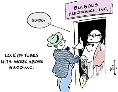
 A usable crystal-controlled signal derived from fundamental-type crystals may
be obtained from two triodes at both 28 and 50 Mc., while at 144 Mc. at least three
triodes must be used with fundamental crystals, or else special harmonic crystals
- often hard to get - must be used. Reasonably good receiver noise figures can be
obtained at 28 and 50 Mc. with conventional circuits, while at 144 Mc. special circuits,
usually requiring one more tube, must be used. Band-switching equipment of reasonable
efficiency can be made to operate at 50 Mc. and lower, but it is very difficult
to design band-switching circuits that include 144 Mc.
TThese considerations conspire to give a strong indictment against the 144 Mc.
band. The choice between the 28- and 50-Mc. bands is not so clear, but in the opinion
of this writer the advantage seems to be in favor of 50 Mc., especially if one also
remembers that the total frequency space available there is larger. These conclusions
are not likely to be popular, because the 50-Mc. band has not been as widely used
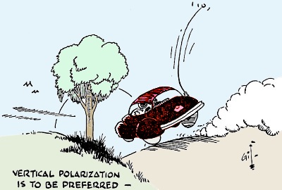
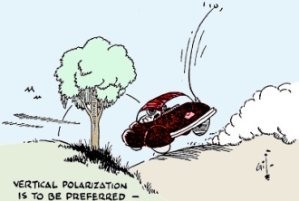
for mobile and civil defense purposes as either of the other two bands. Furthermore,
most of the existing operation on 50 Mc. is with horizontally polarized antennas,
while for mobile use vertical polarization is to be preferred. Unpopular as they
may be, the conclusions are in the opinion of this writer technically sound. Unfortunately,
it may be too late in most cases to change nets that have already been established,
but new ones are still in a position to consider these remarks.
Development of the U.H.F. and Microwave Bands
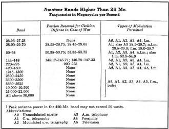
Below 30 Mc. there are seven frequency bands,
containing the major portion of all amateur activity. Above 30 Mc. there are eleven
bands which, except for 50 and 144 Mc., are largely unused. (For convenience the
amateur bands, except for the five lowest ones, are listed in the accompanying table.)
It seems desirable to formulate plans for the use of this large assignment of frequency
rather than to leave it for haphazard development without benefit of all the knowledge
now available concerning these frequencies.
Generally speaking, in the development of the lower frequency bands there was
a tendency to proceed, as a band became occupied, to the one next higher in frequency.
At that time, techniques were not known and it was necessary to proceed gradually.
Also, the nature of ionospheric propagation is such as to cause the properties of
adjacent bands to be radically different. However, in the present situation a great
deal of information is available concerning techniques, and it is known that there
is no such rapid change in the manner of propagation with frequency. Therefore,
it would seem desirable to select a few widely separated bands on which to concentrate
the efforts of those interested, leaving the intervening bands for later occupancy.
Such a selection involves consideration of many aspects and cannot be made by one
person. However, it is in order to point out some of the important topics and likely
choices.
As stated, the 50-Mc. band seems to be the optimum choice for mobile use. It
is also of interest to fixed stations because of occasional ionospheric propagation
to large distances, although such stations do not profit from as favorable antenna
factors as they might obtain at higher frequencies with antennas of the same size.
 Earlier it was indicated that in practice the best antenna factors for general
coverage fixed-station operation probably can be obtained in the 420-Mc. band. This
alone is an important reason for selecting this band. In addition the frequency
is high enough to have a moderate probability of long distance propagation by "trapping"
in a duct. It is the highest frequency band at which (a) tank circuits employing
lumped LC circuits or open-wire lines may be used; (b) it is practical to employ
high-stability narrow-band modulation techniques; (c) common receiving tubes may
be used; and (d) where tubes with directly heated filaments (the 957 and 958 acorns)
are rated for operation. On the other hand, anyone with an interest in r.f, "plumbing"
and accurate machine work will find it to his advantage to follow his interest.
Some war surplus equipment is in use on this band, and other such equipment now
in use at 144 Mc. - e.g., the SCR-522 - may be modified for use at 420 Mc. by making
the last stage of the transmitter a tripler or by adding a tripler to the present
144-Mc. amplifier. The expected development of the commercial u.h.f, television
bands should make improved tubes available at low cost. The 420-Mc. band is wider,
on a percentage basis, than any of the lower frequency bands except 1.75 and 3.5
Mc., and it is the lowest at which television is permitted. In spite of a disadvantageous
antenna factor of 70 (18 db.) in comparison with the 50-Mc. band, portable operation
employing dipole antennas may still be effected. At present there is a legal limit
of 50 watts peak antenna power, but that should not be a serious handicap. Earlier it was indicated that in practice the best antenna factors for general
coverage fixed-station operation probably can be obtained in the 420-Mc. band. This
alone is an important reason for selecting this band. In addition the frequency
is high enough to have a moderate probability of long distance propagation by "trapping"
in a duct. It is the highest frequency band at which (a) tank circuits employing
lumped LC circuits or open-wire lines may be used; (b) it is practical to employ
high-stability narrow-band modulation techniques; (c) common receiving tubes may
be used; and (d) where tubes with directly heated filaments (the 957 and 958 acorns)
are rated for operation. On the other hand, anyone with an interest in r.f, "plumbing"
and accurate machine work will find it to his advantage to follow his interest.
Some war surplus equipment is in use on this band, and other such equipment now
in use at 144 Mc. - e.g., the SCR-522 - may be modified for use at 420 Mc. by making
the last stage of the transmitter a tripler or by adding a tripler to the present
144-Mc. amplifier. The expected development of the commercial u.h.f, television
bands should make improved tubes available at low cost. The 420-Mc. band is wider,
on a percentage basis, than any of the lower frequency bands except 1.75 and 3.5
Mc., and it is the lowest at which television is permitted. In spite of a disadvantageous
antenna factor of 70 (18 db.) in comparison with the 50-Mc. band, portable operation
employing dipole antennas may still be effected. At present there is a legal limit
of 50 watts peak antenna power, but that should not be a serious handicap.
On the other hand, the 220-Mc. band has certain advantages over 420-Mc. Under
practical conditions, one probably cannot quite obtain the optimum antenna factors.
Nevertheless, higher transmitter powers can be obtained, partly by greater efficiency
and partly by the absence of the 50-watt legal limit, and probably one less multiplier
stage is required in a crystal controlled transmitter. At the same time receiver
noise figures may be a bit better. Finally, this band, in contrast to the 420-Mc.
band, has been reserved for civil defense so that any equipment for use on it may
be of value in time of emergency.
The 144-Mc, band, which has the greatest occupancy of any of the v.h.f. bands,
suffers by being "neither fish nor fowl." The antenna factors are inferior to those
at 50 Mc. for portable operation, and to those at 220 and 420 Mc. for fixed stations.
Also, ionospheric or atmospheric effects tending to give extended range are more
probable at both lower and higher frequencies.
 In the 1215-Mc. band and above the antenna
factors tend to favor point-to-point operation on a prearranged schedule. In other
respects the techniques change. Because of radiation losses it is no longer possible
to use open-wire transmission lines as tank circuits. Coaxial lines and, finally,
hollow cavities must be used, and as the frequency is raised greater accuracy must
be employed in the machining of parts. Yet this situation presents a challenge to
enterprising individuals with a mind to mechanical precision. A lathe is almost
a necessity. Perhaps some radio clubs having a number of members with interest in
u.h.f. might consider owning a lathe, although if one is obtained its use should
be closely supervised to prevent damage to it and injury to inexperienced users.
On the other hand, if cavities or other r.f. "plumbing" line components are purchased
at other than war surplus prices the cost is fantastically high, since these items
have never been mass-produced for the retail market. At current prices, for example,
a wave-guide crystal mount costs $125, while the cavity for a 2K28 "McNally" reflex
klystron costs $300 (although the latter is somewhat more elaborate than would be
necessary for amateur use). In the 1215-Mc. band and above the antenna
factors tend to favor point-to-point operation on a prearranged schedule. In other
respects the techniques change. Because of radiation losses it is no longer possible
to use open-wire transmission lines as tank circuits. Coaxial lines and, finally,
hollow cavities must be used, and as the frequency is raised greater accuracy must
be employed in the machining of parts. Yet this situation presents a challenge to
enterprising individuals with a mind to mechanical precision. A lathe is almost
a necessity. Perhaps some radio clubs having a number of members with interest in
u.h.f. might consider owning a lathe, although if one is obtained its use should
be closely supervised to prevent damage to it and injury to inexperienced users.
On the other hand, if cavities or other r.f. "plumbing" line components are purchased
at other than war surplus prices the cost is fantastically high, since these items
have never been mass-produced for the retail market. At current prices, for example,
a wave-guide crystal mount costs $125, while the cavity for a 2K28 "McNally" reflex
klystron costs $300 (although the latter is somewhat more elaborate than would be
necessary for amateur use).
Above 3750 Mc. all tubes in general use are of the "integral cavity" type: that
is, their tuned circuits are largely, and usually completely, contained within the
vacuum envelope, and they can cover a frequency range of ten per cent or less. In
fact, many of the traveling-wave mag-netrons have no tuning adjustment at all, and
the only way one may change frequency is to use another tube. Integral-cavity klystrons
and magnetrons have appeared on the surplus market for frequencies up to 30,000
Mc., but practically none of these lies within the assigned amateur bands. However,
there are a few integral-cavity types which lie within the 3300-Mc. band. In addition.
the 707B or 2K28 "McNally" klystron using an external cavity can be made to operate
in this band. Also, it is possible that lighthouse tubes, especially if selected
and if used in pulsed operation, may be persuaded to operate here. In the 2300-Mc.
band and below, integral-cavity tubes are not generally available. The McNally tube
and lighthouse tubes will operate in the 2300-Mc. band, and in the 1215-Mc. band
they will be joined by "pencil" triodes and possibly selected 6F4 and 6L4 acorn
tubes, whose rated upper limit is 1200 Mc. The machining of a McNally tube cavity
for 3300 or 2300 Mc. may be somewhat easier than a cavity for 1215 Mc. because tuning
at the higher frequency is accomplished by simple screws penetrating the cavity,
while at 1215 Mc. tuned circuits involve coaxial lines which must be tuned by a
plunger with sliding contacts. External-cavity klystrons that can be made to operate
at frequencies above 3750 Me. have recently been developed, but probably these cannot
be obtained without a priority and then only at a high price.
 From the preceding discussion it may be
concluded that widespread use of bands higher than 3300 Mc. appears impractical
because of the lack of inexpensive tubes. Of the bands above 420 Mc. left for consideration,
the 3300-Mc. one appears to hold more interest partly because it is the highest
frequency practical with present components and partly because of the variety of
tube types which might be employed. However, it is to be noted that the 1215-Mc.
band is the lowest one at which pulsed operation is permitted. For general coverage
with this type of modulation this band might be preferred. Should tubes and other
components become readily available for the higher frequency bands, the 10,000-Mc.
band might have some appeal since here waveguide techniques become very convenient.3
The propagation properties differ appreciably from 3300 Mc., and the frequency is
low enough not to suffer appreciable absorption by water vapor. From the preceding discussion it may be
concluded that widespread use of bands higher than 3300 Mc. appears impractical
because of the lack of inexpensive tubes. Of the bands above 420 Mc. left for consideration,
the 3300-Mc. one appears to hold more interest partly because it is the highest
frequency practical with present components and partly because of the variety of
tube types which might be employed. However, it is to be noted that the 1215-Mc.
band is the lowest one at which pulsed operation is permitted. For general coverage
with this type of modulation this band might be preferred. Should tubes and other
components become readily available for the higher frequency bands, the 10,000-Mc.
band might have some appeal since here waveguide techniques become very convenient.3
The propagation properties differ appreciably from 3300 Mc., and the frequency is
low enough not to suffer appreciable absorption by water vapor.
To summarize, if one may forget present usage and select three bands for concentrated
development there would be considerable argument in favor of: (1) the 50-Mc. band
for portable use and occasional ionospheric and tropospheric propagation; (2) 420
Mc. for fixed-station general coverage, with the possibility of television and wide-band
f.m. as well as high-stability narrow-band a.m. and occasional propagation by ducts;
(3) 3300 Mc. preferably for pulsed operation and also preferably for point-to-point
work on prearranged schedules, with considerable probability of propagation by ducts.
While no one can deny the very great advantages to be obtained by the use of
the best available techniques, modulated oscillators and super-regenerative receivers
have a certain amount of appeal especially among beginners or those whose interest
in the higher frequencies is casual. When there are so many virtually unoccupied
bands it would seem a little too bad not to reserve one region where such techniques
might be employed. Because of its large width the 420-Mc. band offers an advantage.
Perhaps the portion 420 to 432 Mc., which is not in harmonic relation to the 144-
and 220-Mc. bands, could be used for this purpose. On the other hand, the needs
of civilian defense might well be served by such techniques if nothing else were
available, and it might be preferable to reserve the 220-Mc. band for this use.
Appendix on Line-of-Sight Range
With two important and mathematically simple exceptions, no formulas have been
used since it is assumed that many readers will not care to follow extensive calculations.
However, for those readers who have more mathematical minds, it is desirable to
put some of the preceding arguments on a more rigorous basis by repeating here the
derivation of the well-known "one-way transmission equation." At the same time it
can be shown that the theoretical line-of-sight range obtainable with small amounts
of power is much larger than one might otherwise expect. Therefore, for local communication
it is practical to employ very low power.
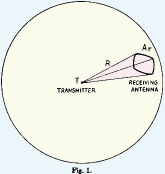 With reference to Fig. 1, let us suppose
that at T there is a transmitter of power Pt. In the case of pulsed transmitters
of low duty cycle, there is a question as to whether Pt should represent
the average power, the peak power, or an intermediate value. If the receiver bandwidth
is adequate to pass the pulses with little distortion, to a good approximation Pt
should represent the peak power. With the types of modulation conventional at lower
frequencies Pt would represent the carrier power. Let us suppose atmospheric
absorption may be neglected. With reference to Fig. 1, let us suppose
that at T there is a transmitter of power Pt. In the case of pulsed transmitters
of low duty cycle, there is a question as to whether Pt should represent
the average power, the peak power, or an intermediate value. If the receiver bandwidth
is adequate to pass the pulses with little distortion, to a good approximation Pt
should represent the peak power. With the types of modulation conventional at lower
frequencies Pt would represent the carrier power. Let us suppose atmospheric
absorption may be neglected.
For the moment it will also be assumed that the transmitting antenna is "isotropic."
Therefore, the fields produced at one instant at the transmitter travel outward
and at a later time will be evenly distributed over the surface of a sphere. The
receiving antenna is at a distance R. When it is connected to a load equal to its
radiation resistance and given optimum orientation, its ability to absorb radiation
is characterized by an equivalent area Ar. The received power Pr
will be Pt multiplied by the ratio of Ar to the area of a
sphere of radius R or

In practice, the transmitting antenna is not isotropic but has a gain Gt
when oriented in the optimum manner. Therefore, we may write

Equation (3A) is given in terms of the gain of the transmitting antenna and the
equivalent area of the receiving antenna and therefore corresponds to special case
(3) discussed in the first article of this series. In confirmation of the remarks
in that article it is observed that the wavelength does not appear in Equation (3A).
By use of Equation (1) of the first article, Ar may be expressed in
terms of the gain of the receiving antenna Gr:

Then Equation (3A) is transformed into a form corresponding to Case (1):

It is to be noted that, in accord with the first article, the received power
is proportional to the square of the wavelength.
Finally, Equation (3A) may be put in a form corresponding to Case (2) by expressing
Gt in terms of the equivalent area At:

The wavelength dependence is again in accord with the first article.
The theoretical limiting range for line-of-sight operation with no atmospheric
absorption will occur when Pr is approximately equal to the equivalent
noise of the receiver
Pr = FkTB,
(4)
where F = noise figure of receiver expressed as a ratio,
B = noise bandwidth, which may be taken approximately as the half-power bandwidth
of the i.f. amplifier in most practical cases,
k = Boltzmann's constant,
T = Absolute "room" temperature.
If B is expressed in kilocycles per second, KT may be taken as 4 X 10-18
watts per kilocycle.
The range may be found by equating the values for Pr in Equations
(3B) and (4) and solving for R:

This is the so-called one-way transmission equation.4 In this form,
R has the same units as A. The gains of the antennas may be expressed in terms of
the equivalent areas by use of Equation (1).
A form of Equation (5) more convenient for numerical computation may be obtained
by expressing the wavelength λ in terms of the frequency, changing some of
the units and lumping all of the numerical constants into a single factor:
wherein R = range in miles,
f = frequency in Mc. per sec.,
B = noise bandwidth of receiver in kc. per sec.,
Pt = transmitter power in watts,
F = noise figure of receiver expressed as a ratio,
and Gt and Gr are respectively the gains of the transmitting
and receiving antennas expressed as ratios with respect to an isotropic antenna.
It is of interest to substitute some conservative values into this equation.
For example, if the following values are used:
Pt = 1 watt,
f = 30 Mc. per sec.,
B = 10 kc. per sec.,
F = 5 (7 db.),
Gt = Gr = 1.64 (corresponding to half-wave dipoles),
the computed value of R has the fantastic value of about 57,000 miles, approximately
twice the circumference of the earth! Of course, such line-of-sight ranges have
no practical direct meaning. However, it is to be expected that under extremely
good ionospheric conditions absorption should be small and the observed range should
approach the theoretical line-of-sight range. Therefore, it is no wonder that since
the very start of international DX amateurs have frequently reported contacts of
several thousands of miles while using powers of the order of only one watt.
At the same time this calculation implies
that at line-of-sight ranges obtainable from practical locations the signal-to-noise
ratio is very large even with such conservative values of the parameters as are
used in the present calculation. For example, at 15 miles the signal-to-noise ratio
would be about 60 (18 db.) if the stations were "in sight" of each other, while
at 5 miles the signal-to-noise ratio would be 540 (27 db.). Hence, at these closer
separations one may infer there is sufficient reserve signal strength to permit
one or both stations to be in partially screened locations.
Furthermore, it can be concluded that if one is primarily interested in local
communication, as is the case in most civilian defense work, practical results may
be achieved by the use of very low power. The present need appears to be for a large
quantity of low-powered equipment rather than a small amount of high-powered equipment.
Also, it is to be remembered that in an emergency gasoline for battery charging
may be scarce or not available, and high-powered transmitters may be nearly useless.
Under these conditions there is much to be said in favor of midget transmitters
employing available receiving tubes with powers of a watt or two. Such equipment
may be simplified and be made more economical by having the transmitter "borrow"
its power from an automobile broadcast receiver.
During the last three years this writer has used mobile equipment of this type,
at first using a 6AK5 final on 28 Mc. with 1.5 watts, and later a bandswitching
affair employing a 6AQ5 doubler with 4 watts, contained in a 4 X 5 X 6-inch box
along with a 6J6 converter. Most of the time the antenna was the standard Ford 54-inch
b.c. whip. Ranges of 5 or 10 miles have been quite consistent on 28 Mc., and on
rare occasions contacts up to 70 miles have taken place. This equipment has been
used in local AREC drills and has usually effected communication from typical city
locations of a few miles. While there is no doubt that the higher-powered stations
have put through louder signals, only rarely has this low-powered equipment been
unable to get through. The operators of stations worked have frequently expressed
surprise at the strength of the signal, and a few have questioned the writer's sanity.
This writer makes no general claim on the latter point, but it happens that theory
has given a valid justification for the use of such low power, and all of the writer's
results are in complete accord with what the theory predicts.
Author's Notes:
In the first article of this series, on pages 42 and 43 of the February, 1952,
QST, it was incorrectly stated that the equivalent area of a bidirectional broadside
antenna is approximately equal to the geometrical area, while a correct statement
would he that equivalent area of a unidirectional broadside beam (with a reflector)
is approximately equal to the geometrical area. Therefore, Table I applies to broadside
antennas with reflectors. This error resulted from the author's misinterpretation
of source material which was rectified by his reading page 43 of the new book Antenna
Theory and Practice, by S. A. Chelkunoff and H. T. Friis, John Wiley and Sons, New
York, 1952.
One cartoon contained in the second article of this series on page 32 of the
May, 1952, QST, although not incorrect, did not give the best interpretation of
the text. This cartoon indicates a duct with a maximum of water-vapor density at
some distance above the surface of the water. Probably such ducts do exist on rare
occasions, and when they exist, they can propagate as shown. However, the author
had in mind something which is much more likely: a duct with maximum density at
the surface of the water and decreasing with height. The author realizes the text
was not as definite on this point as it should have been, and therefore the misinterpretation
is quite understandable. - Y. B.
* Associate Professor of Physics, New York University, University Heights, N.
Y.
1 Beers, "The Wavelength Factor," QST, Feb., 1952; "The Wavelength Factor - II,"
QST, May, 1952.
2 See, for example, QST, page 33, October, 1950.
3 The 1951 and 1952 editions of The Radio Amateur's Handbook contain information
concerning the modification of war-surplus 723A/B or 2K25 tubes for use in the 10,000-Mc.
band.
4 This name is to distinguish this equation from an analogous one giving the
range of radar sets, called the "two-way transmission" equation.
Posted March 6, 2023
(updated from original post
on 9/7/2016) |