The Wavelength Factor - Part I |
|
At long last, I finally acquired the February 1952 issue of QST magazine, which contains Part 1 of the three-part "The Wavelength Factor" article series. Author Yardley Beers covers a lot of ground (pun intended) regarding selection of the best transmitter, receiver, and antenna type for the intended purpose, including fixed-to-fixed and/or fixed-to-mobile communications. Part 2 focuses on propagation, modulation, and receivers. Finally, Part 3 covers choice of frequency bands for civil defense and UHF. See "The Wavelength Factor" Part 1, Part II, Part III The Wavelength Factor - Part 1
By Yardley Beers, * W2AWH Good radio operating always requires detailed knowledge of the properties of all wavelengths available and the intelligent choice of the one best suites for a particular purpose. At the present time two general problems facing the amateur fraternity require particular consideration of this subject: (a) selection of the best band for Civil Defense nets, and (b) the development of the microwave bands, which is stimulated by the recent establishment of Technician Class licenses. Superficially, the selection of a baud for Civil Defense and the development of the microwave bands appear unrelated questions. However, the same reasoning may be applied to both, although with completely opposite conclusions. It will be shown partly in this article and partly in others to follow that, except for ionospheric communication, there is every advantage in placing mobile operation on the longest possible wavelength, while the u.h.f. and microwave bands are suited for fixed-station operation partly because of the necessity for using high-gain antennas with narrow beam widths and partly because of the complexity of the apparatus required to exploit the chief advantages of these very short waves. The choice of the optimum wavelength for a given type of communication - fixed station to mobile, fixed to fixed, etc.- is considered objectively, based on known principles of antenna operation. The conclusions that logically follow may be surprising to many amateurs, especially those not familiar with the "effective area" concept. Although the discussion here and in subsequent articles principally deals with v.h.f.. and u.h.f., the low-frequency man will find it of considerable interest, too. At the lower frequencies the choice is based primarily on the ionospheric properties of the various bands, as these are by far the most important. However, at frequencies greater than 50 Mc. - as well as in ground-wave operation at lower frequencies, where the ionosphere plays no part - the principal factors governing the choice of a band are instrumental: that is, the characteristics of the transmitter, receiver, and especially the antennas, although there are also some effects produced by the lower atmosphere. For sky-wave operation at the lower frequencies the instrumental effects are also present, of course, but to a large extent are obscured by the ionospheric ones. The purpose of this article is to review these instrumental effects in the hope of aiding the solution of the problems mentioned above. Ionospheric effects at the lower frequencies will not be discussed: those readers whose main interest is in sky-wave communication may nevertheless find some of the topics to be of value. Most of the instrumental factors are very familiar by name. A list of the more important ones follows:
The Antenna Factors Before going any further let us define a few terms to prevent confusion. Not all of the power supplied to a transmitting antenna is radiated. Some of it heats up the metal conductors of the antenna. The ratio of the total power radiated to the total power supplied is the efficiency of the antenna. The radiated power, however, is distributed over many different directions. The ability of the antenna to concentrate its radiated power in a preferred direction or directions is called the gain of the antenna. More quantitatively, the gain of an antenna is specified with reference to a standard antenna. It is the ratio of the power radiated (per unit solid angle) in the preferred direction, by the antenna in question, to the power radiated in the preferred direction by the standard antenna. It is assumed, of course, that the total power radiated in all directions is the same for both antennas. The definitions of efficiency and gain of receiving antennas are similar. The efficiency is the ratio of the power supplied to the input terminals of the receiver to the total power extracted from the radiation. The gain is the ability of the antenna to discriminate in favor of signals coming from a desired direction or directions over signals coming from other directions and is usually specified numerically with respect to a standard antenna. As a result of the so-called "reciprocity theorem," the directional properties of a given antenna are the same when it is used as a receiving antenna as when it is used as transmitting antenna. Therefore, the numerical values of the gain are the same for both applications. Two types of antennas are used as a standard for the specification of gain. One of these is an imaginary antenna which would radiate equally well in all directions, called an "isotropic" antenna. The other is a half-wave dipole, which has zero radiation along its axis and a maximum in the plane at right angles to the axis. The power radiated (per unit solid angle) in the directions of maximum radiation of a half-wave dipole is 1.64 times (2.1 db.) that radiated in any direction by an isotropic antenna radiating the same total power. Therefore, gains expressed in terms of the isotropic antenna may be expressed with respect to a half-wave dipole by dividing by 1.64 (or subtracting 2.1 db.). In the present article the isotropic antenna will be used as a standard. With these definitions in mind we shall explain why the equivalent area of a receiving antenna depends upon the wavelength. Let us suppose that we have a receiving antenna of some definite type - for example, a three-element broadside array - pointed at a transmitter. Then suppose that the wavelength of the transmitter is doubled, keeping the efficiency and gain of the transmitting antenna and the power of the transmitter the same. No longer will our receiving broadside array operate correctly. We must double both the element length and the spacing. In doing this we do not change the directive properties nor the gain. Nevertheless, the array "looks bigger" to the transmitting antenna and therefore is more effective in intercepting the radiation, just as a large pan will collect more water in a rain-storm than a small pan. We shall defer a precise definition of equivalent area to a later article. When this is done, there is a very simple formula1 relating the gain, G, the equivalent area, Α, and the wavelength, λ: A = Gλ2/4π (1)
Finally, in the case of large broadside arrays, horns, and parabolic-mirror antennas, the effective area is between 40 and 100 per cent of the actual geometrical area of cross-section of the antenna. Therefore, the effectiveness of these antennas for receiving depends primarily on their geometrical areas. For example, if we replace a large broadside array by another one having the same area but operating at twice the wavelength, to operate correctly the new array requires elements of twice the length and twice the spacing, and therefore will have approximately one quarter the number of elements. Because of the smaller number of elements the gain will be reduced and the beam width will be greater. In order that Equation (1) will be satisfied we conclude that the gain must have been reduced by a factor of 4, and in general we may conclude that for antennas of the types mentioned having constant area the gain varies inversely with the square of the wavelength. It can be inferred that much of this reasoning also applies to end-fire and linear arrays, except for the fact that with them there is no related geometrical area that may be so clearly identified with the equivalent area. It may be concluded that the effectiveness of a receiving antenna - that is, its equivalent area - (a) increases with the square of the wavelength if the antenna has constant gain, and therefore the wavelength from this point of view should be as long as possible, while (b) it is independent of the wavelength if the antenna is a directional array of constant geometrical area. The Transmitting Antenna While the strength of the received signal depends on the equivalent area, of the receiving antenna, its dependence upon the properties of a high-efficiency transmitting antenna is through the gain. Therefore, many of our previous arguments have to be reversed when applied to transmitting antennas. As long as the transmitting-antenna gain is constant, there is no advantage of any wavelength over another so far as the transmitting antenna is concerned. But, if we are limited to a definite size - or, more exactly, a definite area - we see that the wavelength should be as short as possible because the gain varies inversely with the square of the wavelength. However, if we attempt to operate with antennas of very high gain we must expect that as the gain increases the beam width will become narrower, and for certain purposes it may become so narrow as to give difficulty. For example, a parabolic mirror antenna 3 feet in diameter operating in the 3300-Mc. band (9 cm. wavelength) would have a gain of approximately 800 (or 29 db.) and a beam width of approximately 7 degrees between the extreme directions at which the power gain is one-half maximum. The difficulties in general coverage operation without prearranged schedules, using an antenna with a beam width of only 7 degrees, may be seen by comparison with the following angles: The New York City limits (not including suburbs) would subtend an angle of 15 degrees from Philadelphia (75 miles away) and 7 degrees from Boston (180 miles away). Also, Los Angeles and San Francisco differ in direction as "viewed" from New York by 7 degrees. Some alleviation could be obtained by using an antenna with greater vertical directivity than horizontal. However, there is a practical limit to usable vertical directivity because of errors in alignment, unevenness of the ground, and atmospheric effects. This writer would guess that a vertical beam width of 10 degrees and a horizontal width of 45 degrees would be the most narrow beam that could be tolerated in operation without prearranged schedules. In the case of parabolic mirrors and horns., the beam width, θ, in degrees, is given approximately by a simple formula: θ = 2.3λ/d, (2) where the wavelength, λ, is expressed in centimeters, This formula applies to antennas of circular cross-section, strictly speaking.2 In this cased is the diameter expressed in feet. However, little additional error is introduced if the formula is applied to antennas of rectangular cross-section. In this case d represents the dimension in feet corresponding to the plane in which θ is measured. Thus for the horizontal beam width, d would represent the width of the antenna. Probably the error in this formula is not greater than 25 per cent for antennas which are adjusted correctly. More accurate formulas would take into consideration the exact shape as well as other details neglected in the present article.
The upper limit on the size of an antenna depends upon the financial resources and mechanical skill of the builder. Undoubtedly, the following figures can be or have been exceeded, but it is unlikely that antennas larger than those indicated would be built often. A mirror or horn 5.7 feet by 1.7 feet is of practical size, but ones 16 feet, by 3.6 feet would be too large for convenience. Therefore, the 1215-Mc. band is probably the lowest frequency where antennas of this type and beam width would be used. However, because of its open construction a broadside antenna 16 feet by 3.6 feet and having about 4.0 half-wave elements for the 420-Mc. band is within the possibility of practical construction. Such an antenna would have approximately the same equivalent area and gain, but it would be bidirectional and therefore it is to be presumed that the major lobes would be somewhat narrower than 45 X 10 degrees. By adding a group of elements to act as reflectors the array could be made unidirectional, but then the gain would be somewhat greater and the beam width somewhat smaller than 45 X 10 degrees. This could be corrected by reducing the cross-section of the antenna slightly. The adjustment of an antenna with 40 elements is, of course, a problem but not an insurmountable one. These arguments tend to indicate that an antenna of the minimum usable beam width and maximum gain for general coverage operation is within the realm of practical possibility for the 420-Mc. band. At the same time it may be inferred that such an antenna for 220 Mc. would be too large for the resources generally available.
Dipoles, "Super-Gain" Antennas, and Unorthodox Antennas As mentioned previously, the gain of a half-wave dipole is 1.64 relative to an isotropic antenna. Its equivalent area then may be calculated by substituting this value into Equation (1). Since by definition the length is one-half wavelength, we may conclude that the equivalent area depends upon the geometrical size of the antenna. Thus the properties of the half-wave dipole are not in contradiction with any of the ideas we have considered. If we now consider what happens if we replace a half-wave dipole by one considerably shorter, we shall encounter a situation which is very different in several respects. The radiation pattern of a "short" dipole in free space is similar in general to that of the half-wave dipole, having a zero along the axis and a maximum in the plane at right angles to the axis. However, in detail the pattern is slightly different, resulting in a gain of 1.5 (or 1.7 db.) instead of 1.64 (or 2.1 db.). Thus the gain of the short dipole is 0.91 (or minus 0.4 db.) relative to the half-wave dipole. If we substitute the value G = 1.5 into Equation (1), we find for the equivalent area 1.5λ2/4π while for the half-wave dipole we would have the factor 1.5 replaced by 1.64. However, we are no longer required by definition to change the length of the dipole every time we change the wavelength, and therefore we conclude, that with the short dipole both the gain and equivalent area are independent of the geometrical size. Furthermore, it would appear that by replacing a half-wave dipole by one very much shorter we still have an antenna that is 91 per cent as effective in both transmitting and receiving! This conclusion is difficult to believe; although to a large extent it is true. However, this situation requires us to consider a matter that we have been able to overlook up to now: the efficiency.
It, is true that the voltage developed across the terminals of a perfect voltmeter connected to a short dipole will increase in proportion to the length of the dipole. However, the radiation resistance also varies with the square of the length in order to keep the available power and therefore the equivalent area independent, of the length, as required by our formula. Therefore, as we decrease the length of an already "short" dipole while keeping the wavelength constant, the radiation resistance will drop until it becomes comparable with or even smaller than the equivalent resistance of the rest of the circuit, with a deterioration of efficiency. Some countermeasures may be taken against this loss in efficiency·. On the one hand, we may load the antenna in various ways to raise the radiation resistance. On the other hand, losses may be reduced by using heavy conductors in the antenna and elsewhere, and components of high quality. From the widespread success of 4-Mc. mobile stations·- with 10-foot antennas operating against the car body as ground it may be concluded that dipoles of a twenty-fifth and possibly one-fiftieth of a wavelength can be made of sufficiently great efficiency to be practical. The effect of low antenna resistance and these countermeasures combine to make the circuit very selective, necessitating retuning for very slight changes in frequency. In itself this is not always a disadvantage, since it may result in the suppression of unwanted signals in receiving and suppression of unwanted harmonics in transmitting. However, the design of the coupling circuit may depend in an important way upon parasitic capacities and the L/C ratio in the antenna coupler, factors that ordinarily have little effect. Also, in transmitters very high voltages may be developed across the variable condensers with the result that these may have to have higher voltage ratings than usual with transmitters of the same power. The coils must be of low-loss construction, and changing inductance by shorting turns will result in a serious loss of efficiency. Finally, the performance will be affected by rain and swaying in the wind. Advanced antenna theory indicates that it is possible to build antennas of any desired gain with arbitrarily small size, or at least of much smaller size than is in accord with present practical designs. However, Chu has shown3 that as the size is reduced the radiation resistance of these "supergain" antennas falls, with the result of reduced efficiency and bandwidth. Therefore, while high-gain antennas of small size may exist in theory, the theory also predicts that they will be of limited practicality. Although the short dipole perhaps is not included in the definition of a "supergain'' antenna, its behavior as described above is completely in accord with that of antennas of this type. Incidentally, the reasoning of the previous paragraphs justifies theoretically the success of the many unorthodox antennas put up by amateurs because of lack of adequate space, unsympathetic landlords, or laziness. The requirement that a dipole or a long-wire antenna be cut exactly to "resonance" is to a large extent superstition. The Antenna Factors Summarized The combined effects of the transmitting and receiving antennas as dependent upon the wavelength may be summarized conveniently by considering three cases which correspond more or less exactly to most situations likely to be encountered. In the following it is assumed that a mobile station would use a dipole, or at any rate an antenna of very little gain. The question of efficiency will be neglected. 1) Both antennas having constant gain. This situation is likely to be encountered at any wavelength when both stations are mobile, and almost inevitably also by fixed stations at low frequencies. In this case the effectiveness of the transmitting antenna will be independent of wavelength, while the equivalent area of the receiving antenna will increase with the square of the wavelength. Hence in this case the wavelength should be as long as possible. 2) Both antennas of constant size. This is the situation encountered normally with fixed v.h.f. and microwave stations. The equivalent area of the receiving antenna will be independent of the wavelength while the gain of the transmitting antenna will increase inversely with the square of the wavelength. Therefore, the wavelength should be as short as possible, provided that the beam widths do not become too narrow. According to the considerations of Table I, we may conclude that the most favorable antenna factors for general coverage operation would be realized in the 420-Mc. band under practical conditions. For point-to-point operation on prearranged schedules, much higher frequencies would be desirable. 3) Station A having antenna of fixed gain, while Station B has antenna of fixed size. This might be encountered with a fixed station with a rotary beam antenna in communication with a mobile station. When Station A transmits, the gain of the transmitting antenna and the equivalent area of the receiving antenna are both independent of the wavelength. When Station B transmits, the gain of the transmitting antenna varies inversely with the square of the wavelength, but this is compensated exactly by the equivalent area of the receiving antenna, which varies directly with the square of the wavelength. Thus in both cases there is no over-all dependence upon the wavelength. Nevertheless, if the wavelength becomes too short the beam width of Station B will become so narrow that accurate orientation will become difficult. By consideration of these cases we see a very definite group of conclusions: (1) portable and mobile operation should be placed at the longest wavelength feasible; (2) the 420-Mc. band is the band best suited (not utilizing ionospheric effects) for general coverage operation; and (3) the microwave bands are useful mainly for point-to-point operation on prearranged schedules. Although we have only considered the dependence of antenna properties on wavelength so far, it happens by chance that the other factors mentioned at the start of this article conspire almost unanimously to confirm these conclusions. [Editor's Note: Propagation, types of modulation, and equipment limitations will be discussed in a subsequent article.] 1 Although this formula is simple to write and to apply, its proof involves a lengthy application of advanced electromagnetic theory. A proof may be found in Chapters V and VI of Microwave Transmission, by J.C.Slater, McGraw-Hill Book Company, New York, 1942. However, Slater's results are not in the form of our equation, which more recently has been widely used in other books. Slater delines a quantity "the absorption area," which is equal to our "equivalent area" divided by the gain, and he proves that this is equal to λ2/4π for antennas of all types. 2 If θ is measured in radians and if λ and d have the same units, the constant 2.3 is replaced by 1.22. Readers who have taken a college course in elementary physics will then recognize this formula as that for the half angular width of the central maximum of the diffraction pattern of a circular aperture. 3 L. J. Chu, Journal of Applied Physics, Vol. 19, page 1163 (1948). * Associate Professor of Physics, New York University, University Heights, N. Y. Mail address: 4 Ploughman's Bush, Riverdale 71, N. Y.
Posted February 20, 2023 |
|


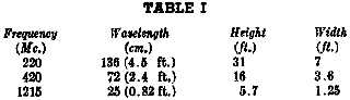 Table I gives the approximate dimensions of parabolic mirror or horn type antennas
which according to Equation (2) would have a horizontal beam width of 45 degrees
and a vertical beam width of 10 degrees for three amateur bands of interest. In
all three eases the gain is about 135 (or 21 db.).
Table I gives the approximate dimensions of parabolic mirror or horn type antennas
which according to Equation (2) would have a horizontal beam width of 45 degrees
and a vertical beam width of 10 degrees for three amateur bands of interest. In
all three eases the gain is about 135 (or 21 db.). 
