The Wavelength Factor - II |
|
In this series, author Yardley Beers discusses propagation effects, modulation systems, and receiver techniques. Part 1 of this 3-part article entitled "Influence of the Antenna of the Choice of Wavelength for Best Communications," appeared in the February 1952 issue of the ARRL's QST magazine. This second part concerns "Propagation, Modulation, and Receivers." I have also posted Part 3, which subsequently appeared in the August 1952 edition. A particularly interesting topic included in this installment is that of using a form of pulse modulation in FM broadcasting in order to exploit the "capture effect" whereby a signal in the presence of noise will tend to suppress the noise. I don't think modern stations use that method, possibly because of incompatibility with stereo channels and data added for digital readouts. See "The Wavelength Factor" Part 1, Part II, Part III The Wavelength Factor - II
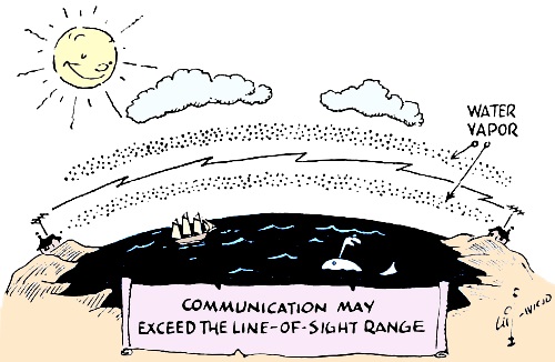
By Yardley Beers, * W2AWH Continuing the survey begun in the February issue, in this article the author takes up the remaining factors that influence the choice of wavelength. The subjects discussed include propagation effects, modulation systems, and receiver techniques. In the preceding article1 the discussion was limited to antenna characteristics as related to the operating wavelength. The remaining factors that influence the choice of a band for a particular type of communication may be grouped under three broad headings: propagation phenomena, types of modulation, and receiver characteristics. These factors will now be considered in turn. Propagation Effects Atmospheric Effects Besides ionospheric effects, which are excluded from this discussion, numerous effects are produced in the atmosphere. First, there is regular refraction and also the well-known refraction caused by temperature inversions. The latter may extend the range well beyond the line of sight at times. One less well-known phenomenon that deserves special mention is superrefraction, "trapping," or "duct" formation. This is due to the formation of a layer containing a gradient of water-vapor density. It is more likely to occur over a large body of water but may also occur over land, especially in evaporation after a rainstorm or during the melting of snow. The existence of such layers is impossible in the presence of strong winds. The general result, normally, is that the rays are bent downward. Then the range of radio communication may exceed several times the line-of-sight range. The necessary conditions arc that (1) the height of the duct must be large compared with the wavelength (several hundred feet for a wavelength of one meter) and (2) the transmitting and receiving antennas be low enough to be contained within the duct. Since small ducts are more probable than large ones, this phenomenon is more likely to produce an effect at the shorter wavelengths. It is primarily of importance at wavelengths below one meter, but on rare occasions it may influence communication even at 10 meters. Stations with antennas above the duct (for example, on a high cliff overlooking a body of water) will find that the formation of a duct will tend to impair communication and give dead spots in their ordinary coverage. Two or more amateurs separated by an over-water path somewhat longer than line-of-sight range might find it of interest to maintain a schedule at 420 Mc., or preferably higher, to investigate this effect. At wavelengths above 10 or 20 cm. the atmosphere is essentially transparent to radio waves. Water vapor has a strong absorption band with a peak at 1.3 cm. and extending, for practical purposes, for several tenths of a centimeter on either side of the peak, depending upon the pressure. Oxygen has a strong absorption band centered at 0.5 cm. Therefore the wavelengths between 0.3 cm. and 1.6 cm. are probably undesirable for radio communication although some interesting refraction effects may accompany the absorption. The oxygen absorption is constant, but the water-vapor absorption will depend on the relative humidity. In addition to these true absorptions, raindrops will cause scattering of radio waves which, practically speaking, is the equivalent of absorption. This scattering increases as the wavelength is reduced, and the effect probably is not large at wavelengths greater than 5 or 10 cm.2 Non-Atmospheric Effects
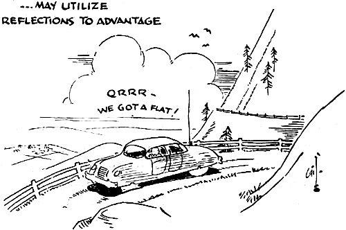
Another effect of some importance is the Doppler effect, which is the change of apparent frequency when the transmitter and receiver are in relative motion. The reader no doubt has heard the whistle of a locomotive as it passed him, resulting in a sudden lowering of the pitch. A similar effect may occur with radio or light waves. If the transmitter and receiver are approaching, the apparent frequency will be raised by an amount equal to the transmitter frequency multiplied by the ratio of the relative speed of motion to the speed of radio waves (186,000 miles per second). If the two are going apart, the frequency will be lowered. Thus at one-meter wavelength (300 Mc.),· a relative speed of 60 miles per hour will give a shift of about 25 cycles, while at 10 cm. the shift will be 250 cycles, and so on. With radar systems this phenomenon may be used to distinguish moving objects from fixed ones. Also it may be used for measuring the speed of projectiles and other bodies. In other applications this effect is a great disadvantage, especially if reflections are present. Rays leaving a moving transmitter in the forward direction may interfere by reflection with others leaving in the backward direction, resulting in an undesirable beat note equal to twice the Doppler shift. Modulation Transmitters employing types of modulation requiring wide frequency channels are usually placed on frequencies higher than 50 Mc. simply because there is no room for them at the lower frequencies. In addition to this very practical reason, there is another one why such systems of modulation should be used at the higher frequencies: frequency instability. The method of using a very stable oscillator at low frequencies, often crystal-controlled, and then employing a chain of multipliers becomes more impractical as the ultimate frequency is raised, and in the u.h.f. and microwave region is generally not practical except for frequency-standard purposes.3 The stability of self-controlled oscillators in this region is probably better, on a percentage basis, because resonant cavities may be built with higher Qs than can be obtained with low-frequency LC circuits. Nevertheless, in terms of cycles per second the drifts may be large. In practice it may be desirable to use receivers with i.f. bandwidths of several hundred kilocycles, or even a megacycle or two, to accommodate frequency drift. These wider bandwidths give rise to increased noise. By employing a system of modulation requiring a comparable or larger bandwidth it is possible, in some cases, to overcome some of the loss of signal-to-noise ratio that accompanies wide bandwidth. Wide-Deviation F.M. The small reflex klystron used normally for local oscillators in microwave receivers, while not very well suited for pulsed operation, has an unusual property which makes it suitable for f.m. The frequency may be varied 10 Mc. or more without a large variation of power by varying the voltage of the repeller by a few volts. Since the repeller is a negative element, it draws no current. Thus effective f.m. can be produced merely by connecting the secondary of a microphone transformer in series. On the other hand, the power supply must be free of hum to a high degree and should be stabilized. The power output of these tubes is generally less than 100 milliwatts, but the high antenna gains practical for point-to-point operation at these frequencies result in ranges of 50 miles or more from suitable loca-tions. Therefore, this type of transmitter offers some possibilities. However, in undertaking work with wide-band f.m., one should understand what such a system can and cannot do. As widely publicized, f.m. "discriminates against noise," but this statement is a half truth, which may lead to wrong conclusions if not understood. The limiting action of a proper f.m. receiver is such that if two signals enter on the same channel, the weaker will be virtually completely suppressed by the stronger. In a similar way, if noise and a bona fide signal are present, the signal will cause the noise to be suppressed almost entirely, while if the noise is stronger the signal will be suppressed. If the two are comparable, as is the case at the end of the range, either may predominate. This latter situation is virtually the equivalent of what takes place with a.m. in similar circumstances. Therefore by substituting f.m. for a.m. and holding the transmitter power and receiver bandwidth constant, the range cannot be increased or decreased to any important extent. However, once the signal is greater than the noise, reception will be much more noise-free with f.m. If the deviation and receiver bandwidth are increased, the effective range will be reduced because the receiver will admit more noise, but once the receiver is well within the limiting range, the noise suppression will be even more complete.
Pulse Modulation Because of the action of detectors in the presence of signal and noise it is advantageous to replace a continuous-carrier system by a pulsed system when the signal is weak compared with noise and when the receiver bandwidth must be kept moderately large to accommodate frequency instability. It may be shown5 that when the signal is weak, even so-called "linear" detectors behave in a nonlinear manner, and the noise tends to suppress the signal. Therefore, with constant average transmitter power it is possible, by replacing a continuous-carrier signal with one containing short pulses of higher peak power, to trade a continually-existing signal which is highly suppressed for one which, although existing for only short durations, can rise above noise. On the other hand, as a pulse is made shorter the spectrum of the sidebands becomes wider, and when the reciprocal of the pulse length in seconds becomes larger than the over-all receiver bandwidth expressed in cycles per second, appreciable portions of the signal are lost. This results in distortion of the pulse shape (notably lengthening) and also a deterioration of the ability to detect the signal in the presence of noise. Thus with a bandwidth of 10 kc. pulse lengths greater than 100 microseconds should be used, while if the bandwidth is 1 Mc., pulses as short as 1 microsecond could be used. In the absence of some extraneous reason there would be little or no advantage to increasing the bandwidth and using shorter pulses, because then more noise would be introduced. In radar systems there is such an extraneous reason since the range resolution - the ability to distinguish two targets in the same direction but differing very little in distance - is improved by using shorter pulses. In simple pulsed communications systems there does not appear to be any such extraneous reason for using pulses shorter than can be accommodated in a receiver bandwidth just great enough to take care of frequency instability.
A simple pulsed telegraphy system could employ a keyed pulsed oscillator whose pulse repetition frequency is in the audio-frequency range, and the receiver would be a conventional a.m. receiver of appropriate input frequency. The pulse repetition frequency would be detected and would appear at the output of the receiver. In the case of triode transmitters the pulsing action could be supplied by grid blocking or "squegging," the same phenomenon which gives rise to self-quenched superregenerative detectors. It would be essential to provide adequate fuses to protect the tube in case the pulsing action failed and the tube either went into continuous oscillation or failed to oscillate at all However, such a system, although very simple, would not give precise control of the pulse shape and repetition frequency. To secure such precise control a vacuum-tube pulsing circuit is required, but this would complicate the apparatus. For use with the microwave magnetrons mentioned above a vacuum-tube pulsing circuit probably is essential. Telephony may be transmitted by pulsed methods using the audio voltage to modulate anyone of the following quantities: pulse amplitude, pulse length, repetition frequency, or the timing of the pulse relative to a marker pulse, the last of these commonly being called "pulse time modulation." In order to permit separation of the audio frequency and the pulse repetition frequency in a filter in the receiver, it is necessary to use a repetition frequency at least three times as large as the highest audio frequency to be transmitted. For the transmission of speech a repetition frequency of at least 15,000 pulses per second is required. In such a situation it would be virtually impossible to use small duty cycles, and therefore it is unlikely that the advantages cited previously in the discussion of pulsed telegraphy could be exploited to any important extent in pulsed telephony. On the other hand, these systems involve the excitation of many sidebands, and therefore in principle a high degree of noise suppression is obtainable when the signal is somewhat larger than the noise just as in the case of wide-deviation f.m. However, the complexity of the circuits required for these types of modulation probably makes them unattractive for amateur communication. For commercial applications pulse time modulation has one important additional advantage. Two or more conversations may be transmitted simultaneously by using one alternate group of pulses for one conversation and another group for a second conversation. In the receiver these may be separated by a properly synchronized "gating" circuit. Receiver Techniques
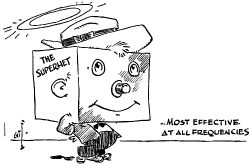
Because crystal converters do not amplify, attention must be paid to the noise properties of the i.f. amplifiers used with them. Furthermore, care must be exercised in the choice of the intermediate frequency. Local oscillators generate noise for a considerable range on either side of the frequency of oscillation, and if the i.f. is too low an appreciable amount of this will be in the signal channel and will be converted by the mixer to i.f. noise. (Also, image discrimination will be poor if the i.f. is too low.) There do exist, however, special balanced circuits employing two crystals for the suppression of local-oscillator noise. On the other hand, if the i.f. is too high, the noise originating in the i.f. amplifier itself may be excessive. At a carrier frequency of 3000 Mc. the optimum i.f. is about 30 Mc. By careful design the natural trend of deterioration of noise figure with the increase of frequency may be confined to surprisingly small limits. Even throughout most of the useful microwave range noise figures of 100 (20 db.) or less may be obtained. It is frequently desirable to sacrifice the high performance of the superheterodyne for simplicity or compactness. At the low frequencies, the regenerative detector, preferably preceded by an r.f. amplifier, is probably the best "second choice." At somewhat higher frequencies the regenerative detector is replaced by the superregenerative detector. In the u.h.f. and microwave range the crystal detector followed by an audio (or video) amplifier using common receiving tubes would probably be the best "second" choice since it avoids the noise of high-frequency tubes and also the complication of the elaborate power supply required by them. [In the third article of this series, to appear in an early issue, the information contained in this and the first article will be utilized in reaching conclusions as to the optimum bands for both general amateur activities and civil defense work. - Ed.] * Associate Professor of Physics, New York University, University Heights, N. Y. 1 Beers, "The Wavelength Factor," QST, February, 1952. 2 More information concerning ducts and absorption in the atmosphere may be found in Chapter 2 of "Radar System Engineering," Vol. 1 of the Radiation Laboratory Series, McGraw-Hill Book Co. Still more extensive information may be found in Vol. 13 of this series, "Propagation of Short Radio Waves." For a discussion of other atmospheric effects, see "Over the Hills and Far Away," by R. K. Moore, QST, Feb., 1951, p. 13, and "V.H.F. - Why - How - When?" Part II, by E. P. Tilton, p. 46, same issue of QST. 3 If about 10 watts of r.f. generated by a (quartz) crystal oscillator and frequency multipliers at 90 Mc. is applied to an "S"-band (silicon) crystal holder, harmonics of more than ample strength for frequency-standard work in the 3000-Mc. region are produced. 4 S. Goldman, "Some Fundamental Considerations Concerning Noise Reduction and Range in Radar and Communication," Proc. I.R.E., Vol. 36, p. 584 (1948). 5 See, for example, Section 7.9 of "Microwave Receivers," edited by S. N. Van Voorhis, McGraw-Hill Book Co., New York,1948.
Posted February 28, 2023 |
|