|
April 1967 Popular Electronics
 Table
of Contents Table
of Contents
Wax nostalgic about and learn from the history of early electronics. See articles
from
Popular Electronics,
published October 1954 - April 1985. All copyrights are hereby acknowledged.
|
In 1967 when this article
article appeared in Popular Electronics magazine, the use of integrated
circuits in consumer electronics was still relatively new. RCA, GE, Westinghouse,
and Philco had just released their first TVs and radios with IC front ends, and
Heathkit even had a build-it-yourself model. The military was using them (ICs) in
proximity fuse designs. The new technology was really cooking. ESD issues were discovered
and needed to be dealt with as gate sizes shrunk and the vulnerability to arcing
became a problem. A photo is shown where NASA developed a method for mitigating
the potential damage by looping a spring-loaded wire around the leads of MOS-based
ICs during handling. A bit of nerd humor is also presented to commemorate the April
edition.
Solid State columns: April 1967,
August 1967,
April 1966,
August 1970,
July 1971,
October 1971,
April 1972.
Solid State
A new manufacturing process at Eburn Industrial Research Corp.
(Hingham, Mass.) allows IC designers to pack 100 times as much circuitry into the
same area occupied by a conventional transistor.
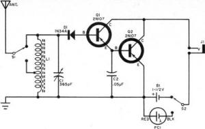
Fig. 1 - Two-transistor AM broadcast-band receiver circuit
submitted by reader Doug Zimmer features a Darlington pair amplifier (Q1 and Q2),
and a power switch that lets you select either a chemical battery, B1, or a sun-powered
battery (PC1).

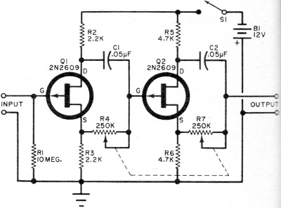
Fig. 2 - One of the many practical FET circuits described
in a recent folder from Siliconix, Inc., each stage of this phase shifter permits
continuous adjustment of phase shifts from 0°·to 180°.

Fig. 3 - This is a simple device used by NASA to protect
MOS transistors from being accidentally damaged by the application of an electrostatic
potential across the leads while the transistor is being handled or assembled in
a circuit. A loop of flexible nickel wire is attached to a music wire spring that
is slipped over the transistor's case and released, shorting together all of the
leads.
Oversize Power Transistor
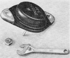
On April 1, the Lou Garner Enterprises announced the development
of the BMB transistor. Rated at a maximum free air dissipation of about 10,000 watts,
the new transistor is shown in the accompanying photograph - note how the elements
dwarf the nut and crescent wrench. Beta values have not been calculated, but the
alpha is reported to be close to 1.0001 under typical operating conditions. Distribution
and quantity prices have not yet been firmly established for this breakthrough.
Withdrawn from Market

Due to production and patent problems, the Lou Garner Enterprises
on April 2 regretfully announced the withdrawal of the super-power transistor. Interest
in this new development was confined to April Fool's Day.
 By Lou Garner, Semiconductor Editor By Lou Garner, Semiconductor Editor
The use of integrated circuits in consumer products is increasing at an accelerated
pace. Last year several major manufacturers started to include IC devices in their
TV sets (RCA) and table-model radio receivers (GE and Philco). Heath followed suit
shortly thereafter with a TV receiver kit featuring an IC. H.H. Scott a major hi-fi
equipment producer, is now using IC's in the i.f. stages of its better line of FM
receivers and tuners. And the latest entrant in the field is Westinghouse Electric
Corp., with an IC portable phonograph. The new phonograph uses a conventional record
changer, but the familiar amplifier has been replaced by an IC measuring only 0.112"
x 0.085" and equivalent, performance-wise, to 39 components, consisting of transistors
diodes, and resistors.
But the IC news is not limited to the domestic front. Two major Japanese manufacturers,
Sony Corp. and Matsushita Electronics Corp., are producing radio receivers using
IC's, and another firm, Victor Co. of Japan Ltd., is selling a 25-inch color TV
set with a hybrid IC in its sound channel.
The Military, too, is going for IC's in a big way, not only in communications
and computer applications but, more recently, in the production of IC proximity
fuses. A World War II development, the proximity fuse is a miniature transceiver
used in artillery shells and bombs. In operation the device senses its approach
to a target by measuring the Doppler shift between shell and target. At a preset
distance, its detector circuit, activated by a reflected radio signal, detonates
the warhead charge.
Another recent development in the field permits smaller firms to design custom
IC's for their own products without the high investment cost of a complete manufacturing
facility. A sort of "do-it-yourself" IC kit the new item is an open-cased monolithic
silicon chip measuring only 0.086" x 0.124" but containing 60 components. The user
interconnects the various elements as needed to assemble his own custom circuit.
Produced by Westinghouse Electric Corp., the IC kit has been dubbed the "Insta-Circuit"
and is available in both flat-pack and TO-5 configurations. Suitable for manufacturers
schools and laboratories, the Insta-Circuit is definitely not a hobbyist item, since
the special microscope-equipped wire bonder required to make the final circuit connections
costs almost as much as a small car. The circuit chips themselves sell for less
than $40 each in unit quantities and less than $30 each in quantities of 50 to 400.
Reader's Circuit. Agreed that simple AM broadcast-band receiver
circuits are literally "a dime a dozen," the circuit in Fig. 1, which was submitted
by reader Doug Zimmer (14332 35th N.E., Seattle, Wash.), combines a number of interesting
features that make it suitable for demonstration or test purposes.
Doug has employed a standard tapped antenna coil, with the tap serving as a means
of matching the antenna. In addition, he has used a Darlington pair amplifier (Q1
and Q2) and a dual d.c. supply, permitting the selection of either a chemical battery
(B1) or a sun-powered battery (PC1) as the power source.
Radio-frequency signals picked up by the antenna are selected by tuned circuit
L1-C1 and detected by diode D1. Switch S1 provides optimum match for both long and
short antennas, insuring the best compromise between selectivity and sensitivity.
The detected audio signal is amplified by Q1 and Q2 and applied to an earphone plugged
into output jack J1. Capacitor C2 serves to bypass the r.f. signal.
Switches S1 and S2 are s.p.d.t. toggle, slide, or rotary types. Coil L1 is a
tapped loopstick antenna coil (Superex VLT-240 or similar) and C1 is a standard
365-pF variable capacitor. A tubular paper capacitor or ceramic unit can be used
for C2; working voltage is not critical. Diode D1 is a general-purpose type similar
to a 1N34A and Q1 and Q2 are low-power pnp types (typically, CK722, 2N107, or SK3003).
An open-circuit phone jack is used for J1.
Either a penlight cell or standard flashlight cell will be suitable for B1; PC1
is an International Rectifier type SIM silicon solar cell. Doug recommends moderate
impedance (500- to 5000-ohm) magnetic earphones. And you can use either a printed
circuit or point-to-point wiring when building this receiver.
Manufacturer's Circuit. An interesting experimental phase shifter
circuit is shown in Fig 2. One of the 20-plus practical circuits described in a
four-page folder recently published by Siliconix, Inc. (1140 W. Evelyn Ave., Sunnyvale,
Calif.), the phase shifter permits a continuous adjustment of the relative phase
difference between its input and output signals. It can be used for test purposes
or to demonstrate the concept of phase shift. It is particularly valuable for demonstrating
the changes in standard Lissajous figures as a signal's phase angle is varied.
The phase shifter consists of two cascaded split-load amplifier stages with appropriate
signal-combining phase-shifting networks between the drain and source output points.
Each stage provides from 0°·to 180° phase shift. Resistor R1 serves as Q1's gate
return resistor and as the input load. Resistors R2 and R5 act as drain loads while
R3 and R6 serve as individual source loads. Combinations C1-R4 and C2-R7 form, respectively,
the first-and second-stage signal-combining network, with the degree of phase shift
determined by their adjustable resistive elements (R4 and R7). Operating power is
furnished by a 12-volt battery, B1, controlled by s.p.s.t. switch S1.
Standard components are used in the instrument. Transistors Q1 and Q2 are FET
2N2609's. All resistors are half-watters; R4 and R7 are ganged potentiometers. Capacitors
C1 and C2 are high-quality ceramic or plastic film types. Switch S1 can be a toggle,
slide, or rotary switch, as preferred. A variety of 12-volt battery power packs
can be used for B1 including two 6-volt portable A types in series, or eight series-connected
penlight or flashlight cells. You can also power the phase shifter with a line-operated
d.c. power supply if you wish.
Observe good wiring practices when assembling the device, and keep all signal
leads short and direct. The "Phase Shifter" can be wired on a suitable etched circuit
board or on a perforated phenolic board, and housed in a small metal utility box.
A sine-wave audio signal generator can be used as the prime signal source for checking
phase shifts.
Transitips. Although possessing extremely - high input impedance,
insulated-gate field-effect transistors (IGT's, IGFET's, MOST's, or MOSFET's) can
be damaged quite easily by stray electrostatic charges. To protect these devices
against such damage during storage and shipment, semiconductor manufacturers use
techniques like wrapping the transistors in foil, twisting or soldering the lead
tips together, or shorting the leads by means of a metal eyelet. However, none of
these techniques provides adequate protection when the transistor is prepared for
installation in a circuit since the leads must then be separated.
A recently published NASA "Tech Brief" describes a simple and inexpensive device
(Fig. 3) for preventing accidental damage when MOSFET's are actually installed
in a circuit. If you do work with these transistors, you may want to use a similar
device. It is made from short pieces of 0.033-inch diameter music wire and 0.007
-inch diameter nickel wire.
First, bend the music wire to form a spring with small end loops. Then, form
the nickel wire into a single loop and attach its outer ends to the spring loops
by twisting and soldering. The spring is compressed during this operation so that
the nickel wire is held under tension.
Squeeze the spring, expanding the nickel wire loop, and slip the loop over the
transistor leads until it touches the case. Then release the spring, tightening
the nickel wire loop and shorting the transistor leads together. You can now remove
the manufacturer's protection feature (slip off the eyelet, untwist the leads, etc.).
Finally, an insulated Transpad is slipped over the transistor's leads and pushed
up against the taut wire loop to serve as a retaining disc.
The protected transistor can now be inserted in its socket and mounted on a circuit
board, or soldered in position. Once the transistor is installed, the protective
device can be removed either by compressing the spring (opening the nickel wire
loop) or clipping the fine nickel wire. And another thing: use a soldering iron
- not a gun - when wiring MOSFET's, and be sure to ground the tip of the iron to
the substrate lead before soldering the gate lead in place.
Until next month ...
Lou
Posted December 16, 2022
(updated
from original post on 9/5/2012)
|