|
October 1958 Popular Electronics
 Table of Contents Table of Contents
Wax nostalgic about and learn from the history of early electronics. See articles
from
Popular Electronics,
published October 1954 - April 1985. All copyrights are hereby acknowledged.
|
After a short review of
the material from Part 1 of "Speaking of Magnetism" that appeared in the August
1958 issue of Popular Electronics, Part 2 delves a bit deeper into the theory
with induction and Lenz's law. For some reason, a lot of
people seem to have a harder time grasping the concepts of magnetics than of electricity.
Maybe it is because most of the machines and appliances we are familiar with run
off of electricity. The fact that motors, transformers, and relays, which are present
in one form or another in every household, office, and factory, are as reliant upon
magnetic effects as they are electrical effects is lost on the multitudes.
This "After Class" article from the October 1958 edition of Popular Electronics
helps bridge the gap of knowledge.
Here is "Speaking of Magnetism"
Part 1
and Part 2.
After Class: Speaking of Magnetism, Part 2
 What kind of force exists between two closely
spaced, parallel, current-carrying wires? Are the wires attracted to one another
or do they repulse each other? Before we attempt to answer these questions, let's
refresh our memories on two simple "hand" rules concerning the direction of a magnetic
field due to a current. What kind of force exists between two closely
spaced, parallel, current-carrying wires? Are the wires attracted to one another
or do they repulse each other? Before we attempt to answer these questions, let's
refresh our memories on two simple "hand" rules concerning the direction of a magnetic
field due to a current.
Rules of Thumb
The first is Oersted's famous rule: if the thumb of the left hand points in the
direction of the electron current in a wire, the fingers then encircle the wire
in the direction of the lines of force (Fig. 1). Small compasses distributed
around the wire show - by the direction in which their little N-poles point - which
way the field is going, and verify Oersted's rule. (If you have encountered this
rule given for the right hand, It must have been in a book that still employs the
old plus-to-minus current flow convention rather than the more modern electron current
idea. See After Class, June, 1958.)
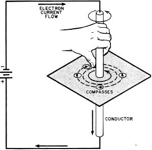
Fig. 1 - Oersted's left-hand rule specifies the direction
of a magnetic field which surrounds a current-carrying conductor.
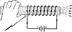
Fig. 2 - The left-hand rule for coils is used in determining
the direction of the magnetic field due to coil current.
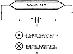
Fig. 3 - Two parallel conductors carrying currents in the
same direction (A). and cross-section convention (B) for showing electron currents
flowing in or out of the plane of the paper.
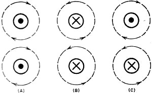
Fig. 4 - Both currents flowing out of the paper produce
two sets of clockwise fields (A); both currents flowing into the paper produce two
sets of counter-clockwise fields (B); and one current flowing into the paper and
the other out of the paper produce oppositely circling fields (C).
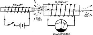
Fig. 5 - A primary magnetic field in the process of growing
toward the right induces an electron current which causes a secondary field to grow
to the left. The galvanometer needle indicates current flow in the secondary coil
winding and the direction of the flow.
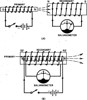
Fig. 6 - With the primary and secondary coils end-to-end
(A). polar approach predicts same induced cur-rent as field approach, but when primary
is inside secondary coil (B). The polar approach gives incorrect induced current
direction.
The second rule of thumb describes the direction of the magnetic field of a solenoid
as related to the current flowing in the coil. If the fingers of the left hand encircle
the coil in the direction of the electron current, then the extended thumb will
point in the direction of the lines of force produced by the solenoid, as in Fig.
2. To distinguish this from Oersted's rule, it is commonly referred to as the "rule
for coils."
Obviously, an electron current traveling upward in the conductor of Fig. 1
would produce a clockwise rather than a counter-clockwise field in the horizontal
plane. If the electron current in the coil turns is reversed, the field direction
will also reverse. Both these turnabouts are, of course, predicted by the applicable
rule.
Using Field Theory
We now have everything we need to solve magnetic force problems of any type using
field theory rather than magnetic poles. Suppose we have two parallel conductors
in which current is flowing in the same direction. Looking at these conductors sidewise,
they appear as shown in Fig. 3 (A).
From this perspective, it is difficult to visualize and draw the lines of force
associated with the current. To make the job substantially easier, we will adopt
a convention that is now universally accepted:
All wires pictured as little circles representing the cross section of the conductor
passing through the plane of the paper at right angles.
If the current direction is out of the paper toward the reader, we imagine that
he sees an arrow point; thus we designate an outward-flowing electron current by
a dot in the center of the circle. For the opposite case, an electron current flowing
into the paper away from the reader, we picture a receding arrow whose tail-feathers
are visible. We show such a current as a cross (for the tail-feathers) in the center
of the circle.
Force Directions
Let us now visualize the two parallel wires of Fig. 3 (A) swung through
90° so that they present a cross-sectional view of two little circles. If the rotation
occurs in one direction, the current will appear to be coming out of the paper toward
the reader, as in Fig. 4 (A). In this case, Oersted's rule tells us that the
magnetic field around each wire is clockwise; between the wires, adjacent lines
of force have opposed directions, giving rise to an attractive force as required
by the fourth characteristic of lines of force (see Part 1, August issue).
If you had pictured the two wires of Fig. 3 (A) swung around the other way,
the electron currents would have had to be shown receding - crosses in the circles
as in Fig. 4 (B)-and the circular fields would then have been counter-clockwise.
Note, however, that this makes no difference in field theory application: the line
directions are still opposite between the wires and the force is again attraction.
Fig. 4(C) illustrates the state of affairs when the current flows in opposite
directions through two parallel wires. Adjacent lines between the two conductors
have the same direction; so a force of repulsion appears between them as predicted
by the second characteristic given for lines of force in Part 1. You can demonstrate
these effects by stretching 8" lengths of #32 or #34 wire about 1 millimeter apart
and connecting their ends to a 6-volt storage battery; the contact should be momentary
to avoid overheating the wires.
These examples lend strength to our contention that polar reasoning must give
way to the field approach merely because you cannot work with magnetic poles if
you can't even find them! Our next example is really the clincher. We will show
that with induced currents, the polar attack leads to two contradictory results.
Induced Currents
Two coils are positioned end-to-end as in Fig. 5. In series with one of
them is a battery and a momentary push button or switch. A sensitive galvanometer
with a center-zero scale is connected in the second coil circuit. When the key is
momentarily pressed, the galvanometer needle swings one way, say to the right, and
when the key is released, the needle swings to the left.
From the principles of electromagnetic induction, we know that while the magnetic
field is building up and out of the first coil (the primary winding), it cuts through
the secondary winding and induces a current. When the key is released, the primary
field collapses, cutting back through the secondary coil and inducing a current
whose direction is opposite from the first. The direction of the induced current
is given by Lenz's law (which, by the way, is merely a restatement of the Law of
Conservation of Energy in electrical terms): an induced current has such a direction
that its magnetic action tends to oppose the motion by which it is produced.
Imagine that the key in Fig. 5 has just been closed so that a surge of electron
current occurs in the direction shown. Using the rule for coils given previously,
we can say that a magnetic field expands outward from the primary as a result of
this current, cutting through the turns of the secondary, The current induced in
the secondary coil, according to Lenz's law, must have such a direction that the
field it produces opposes the initial, expanding field. This current direction -
arrived at by again employing the rule for coils - is indicated by the arrows on
the secondary turns.
When the primary circuit is then opened, the initial field collapses back into
the first coil. This permits us to say that the actual motion of the field is now
the reverse of what it was when the key was closed. To oppose this motion, the current
in the secondary promptly and obligingly turns about and creates a magnetic field
toward the right-in other words, it creates a field that opposes the collapse of
the primary field.
This approach gives the right answer no matter what the relative positions of
the coils may be. It works just as well if the primary coil is inside the secondary,
out-side the secondary, or end-to-end with it.
The Wrong Answer
Now let's see what happens if we try to use polar reasoning. Closing the key
causes a growth of the primary field out of the right side of the coil when the
windings are end-to-end; this necessitates labeling this side of the coil "N" and
the left side "S." (Remember? The N-pole is the side from which the lines emerge.
To oppose the growth of an N-pole on the right side of the primary, an induced
N-pole must form on the left side of the secondary; since like poles repel, opposition
is being produced by repulsion in this instance. See Fig. 6 (A). So the answer
we arrive at for the end-to-end arrangement coincides exactly with the solution
obtained using field theory.
Here's the rub, however. If the primary coil is now inserted coaxially inside
the secondary coil, the polar approach gives the wrong answer. With the expanding
primary field producing an N-pole on its right end, the polar hypothesis demands
that the secondary coil also form a budding N-pole on its right side to oppose the
growth of an adjacent similar pole on the primary coil. Thus, this situation requires
that the induced current in the secondary flow one way when the coils are end-to-end
and in the opposite direction when one is inside the other as in Fig. 6 (B).
This does not happen in practice!
As we showed earlier, field theory makes no distinction between relative positions
of primary and secondary and therefore predicts the correct answer. The polar method,
on the other hand, falls flat in this instance. Conclusion: abandon magnetic poles
and think in terms of magnetic fields!
Posted September 26, 2019(original 9/20/2011)
"After Class" Topics
|