|
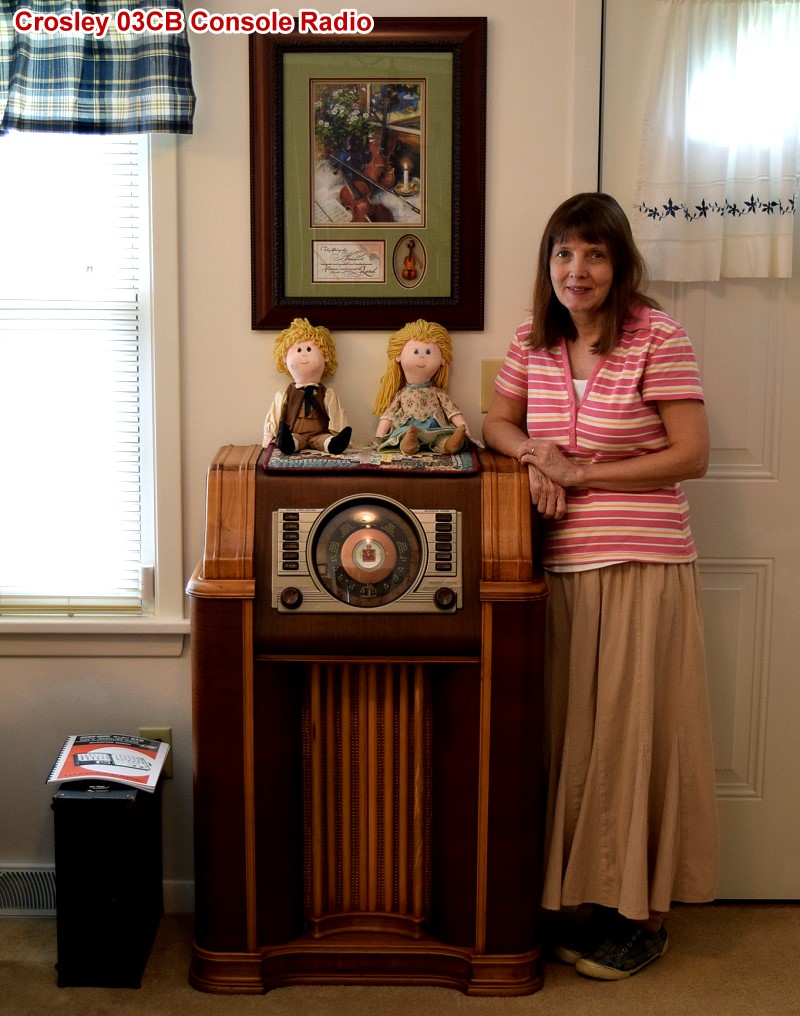
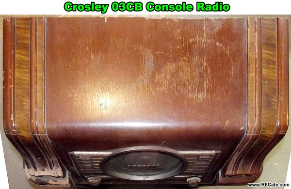
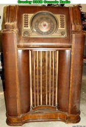
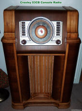
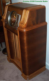
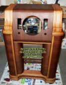
My Crosley 03CB radio restoration is complete!
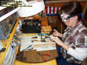
 Melanie with my restored
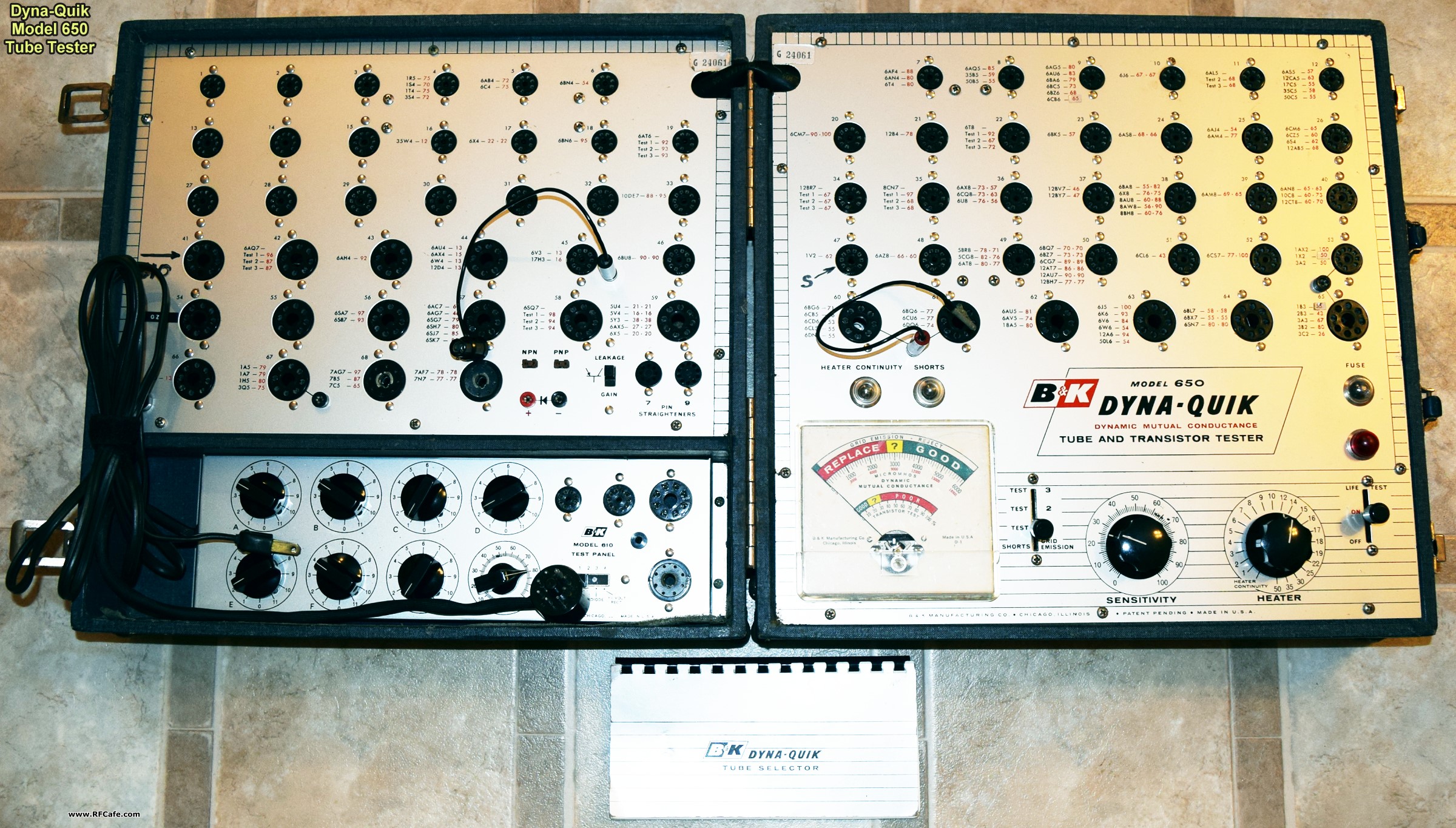
Crosley 03CB console radio. Dyna-Quik Model 650 Tube & Transistor Tester on
floor to the left.
 Melanie and I drove 300 miles from Erie
to Harrisburg, Pennsylvania, back in June of 2013 to pick up this circa 1941, Crosley
03CB floor console model radio. As can be seen in the 'before' photos, it was in
pretty rough condition. The wooden console was dinged and the walnut veneer was
separated and missing in places. A severe overheating condition must have occurred
the last time it was plugged in because the plastic front panel knobs were partially
melted and distorted. Both concentric tuning, band switching, volume, and on/off
switch shafts were rusted together. It was definitely a diamond in the rough. After
a year and a half of wood, metal, and electronics work, it is now what I believe
is one of the finest examples of a restored Crosley 03CB radios in existence. Melanie and I drove 300 miles from Erie
to Harrisburg, Pennsylvania, back in June of 2013 to pick up this circa 1941, Crosley
03CB floor console model radio. As can be seen in the 'before' photos, it was in
pretty rough condition. The wooden console was dinged and the walnut veneer was
separated and missing in places. A severe overheating condition must have occurred
the last time it was plugged in because the plastic front panel knobs were partially
melted and distorted. Both concentric tuning, band switching, volume, and on/off
switch shafts were rusted together. It was definitely a diamond in the rough. After
a year and a half of wood, metal, and electronics work, it is now what I believe
is one of the finest examples of a restored Crosley 03CB radios in existence.
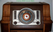
 Mr. Tim O. sent me photos of the
Crosley model 03CB
console (floor) radio that his parents owns and which he remembers listening
to as a kid. Tim says as far as he knows the radio still works. As can be seen in
the images below, it is still in pretty good condition for a 75-year-old radio!
... Mr. Tim O. sent me photos of the
Crosley model 03CB
console (floor) radio that his parents owns and which he remembers listening
to as a kid. Tim says as far as he knows the radio still works. As can be seen in
the images below, it is still in pretty good condition for a 75-year-old radio!
...
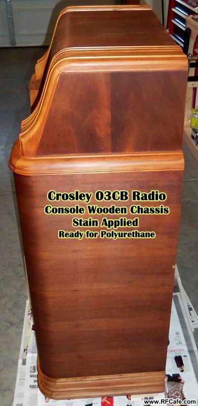
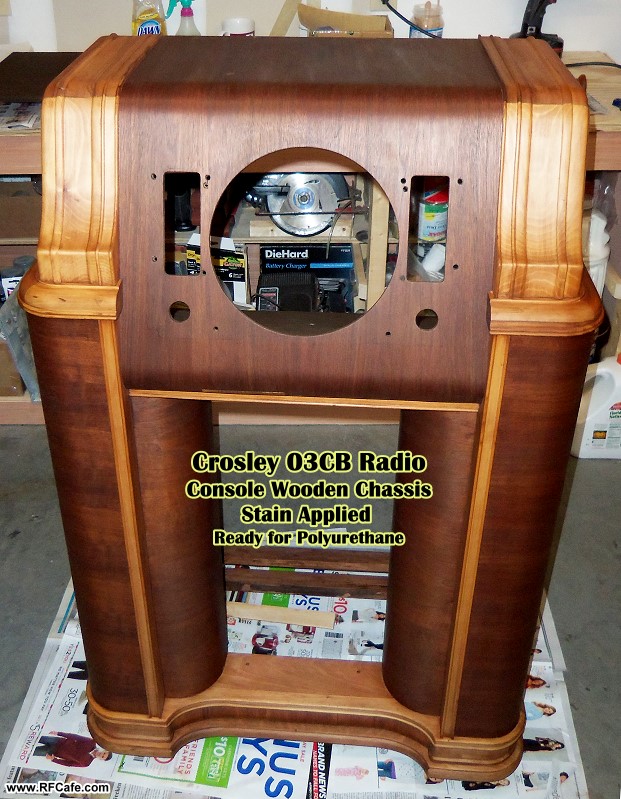
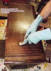
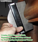
As the photos show, the wood cabinet and metal electronics chassis were completely
stripped of all components. Paint stripper was used to remove all the original finish
from the wood, and then many hours of careful sanding, gluing, and repairing were
performed. The darker areas are walnut veneer, and I'm not certain what the solid
wood parts are made of; it does not appear to be maple, but it is very hard - -maybe
ash. A coat of Minwax Golden Pecan stain was applied over all surface to even out
the coloring. No attempt was made to replicate the striated plastic stencil covering
on the speaker grille rods or the solid wood parts. I decided the risk of screwing
up the wood during a hand painting of the design would not be worth it. Four base
coats of Minwax semi-gloss polyurethane were brushed on, sanding with 220-grit paper
between every coat. Because preventing runs and/or sags on vertical surfaces is
difficult with polyurethane, the final (fifth) coat was sprayed on. The result is
as perfect of a finish as I have ever attained. Use of a tack rag prior to application
helped obtain the nearly dust-free finish.
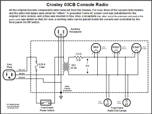
Wiring Diagram of Tube Filaments and Auxiliary AC Power Cord
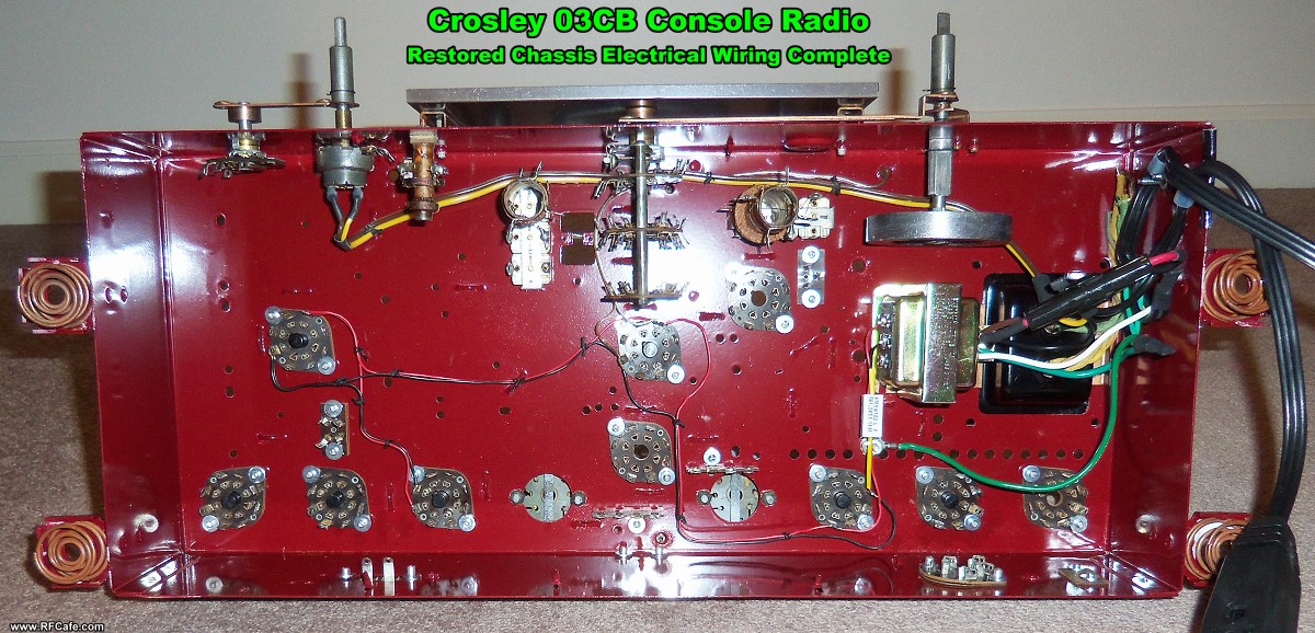
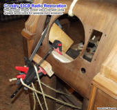
After all of the electronics components were removed from the chassis, it was
sanded to bare metal, primed, and painted with Rustoleum enamel. All of the major
components were cleaned, painted where needed, and reinstalled. Leaded resistors,
capacitors, and inductors were left out - at least for now. If I live long enough
and am motivated to do so, I might someday attempt to get the original circuit working
again. For now, however, I settled for wiring a few of the vacuum tube heaters and
the front panel lamps to light up when the power switch is turned on. A 3-wire power
cord is used with a safety ground connection to the metal parts. I bought an 8'
extension cord and cut it about 18" from the receptacle end, and used the plug section
as the power cord. The receptacle end is on the load side of the power switch and
hanging inside the cabinet so that at some point I can set a working radio inside,
plug it in, and have it be turned on and off by the front panel switch.
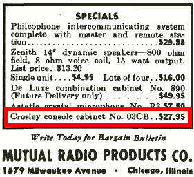
 I have searched extensively
for an advertisement for the Crosley 03CB in magazines and newspapers in the 1940
through 1945 and the most that has appeared thus far is this single line of text
in the July 1943 issue of Radio News. The price makes me wonder if the
cabinet itself was sold without electronics since it uses the same components in
the easy to find 02CA model. I found a second 03CB on Craigslist in Harrisburg,
Pennsylvania, so that makes two from that region. The one featured here on this
page was gotten from (Harrisburg), and my first one was from Maryland. I have searched extensively
for an advertisement for the Crosley 03CB in magazines and newspapers in the 1940
through 1945 and the most that has appeared thus far is this single line of text
in the July 1943 issue of Radio News. The price makes me wonder if the
cabinet itself was sold without electronics since it uses the same components in
the easy to find 02CA model. I found a second 03CB on Craigslist in Harrisburg,
Pennsylvania, so that makes two from that region. The one featured here on this
page was gotten from (Harrisburg), and my first one was from Maryland.
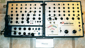

B&K Dyna-Quik Model 650 Vacuum Tube and Transistor Tester
Farther down on the page you can see the postings I made as work progressed.
There are many more photos available with a higher level of detail. If you have
need of anything, please let me know.
Melanie and I have decided to eventually offer the Crosley 03CB to a museum.
We will be doing research into which museum would most benefit from it. This might
well have been one of Crosley's final commercial radios built prior to converting
its factory to wartime radio production. Here is a brief news item from when
Crosley announced it would be scrapping its 1943 line of household
radios to dedicate all production to the war effort.
As the old saying goes, a picture is worth a thousand words, so here are a few
thousand words for you:
|
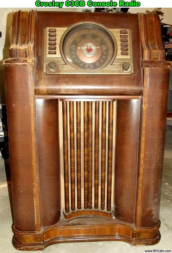
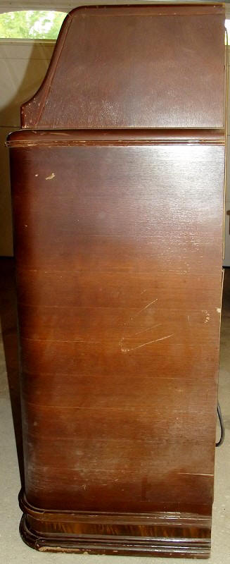
Crosley 03CB - Original
This is how the radio was received.

Crosley 03CB - Original
I never plugged in the original
to test it because there was obvious heat damage.
Crosley 03CB - Original
Note the melted knobs from chassis
overheating.
(Replacement knobs available at renovatedradios.com)

Crosley 03CB - Original
Top of cabinet.

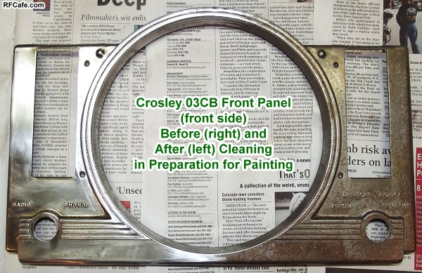
Crosley 03CB
Before and after preparing front panel for
painting. Dupli-Color Desert Sand Mica was used for the base plate, and Arizona
Beige was used for the button trim plates.
Crosley 03CB - Original
Lots of dust!
|
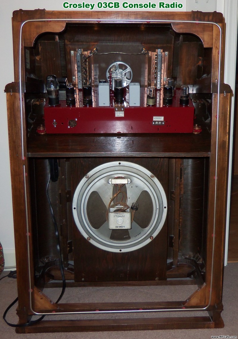
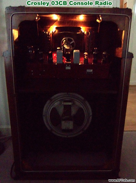
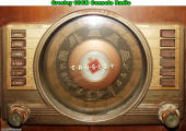
Crosley 03CB - Restored
The final result! (front)

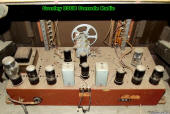
Crosley 03CB - Restored
The final result! (back)
Note
the receptacle end of the extension cord hanging in the left corner, just below
the shelf.
Crosley 03CB - Restored
Replacement knobs were purchased
from RenovatedRadios.com
Crosley 03CB - Restored
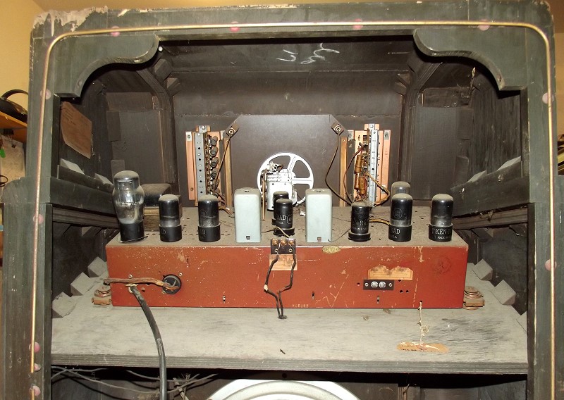
See pics below for chassis restoration
work.

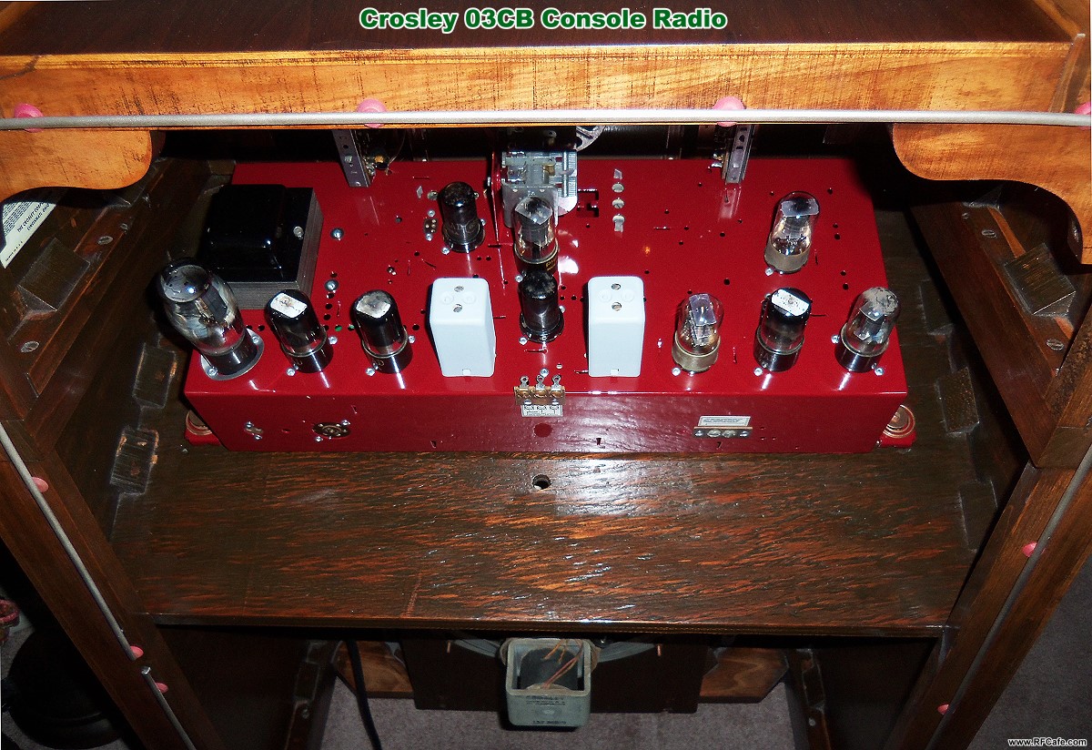
Crosley 03CB - Restored
Electronics chassis wired to light
up some vacuum tube heaters and the front panel lamps.
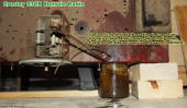
Crosley 03CB - Original
Evapo-Rust used to unstick rusted-together concentric control
shafts.
|
Crosley 03CB - Restored
Right side of cabinet.
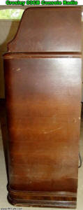
Crosley 03CB - Original
Right side of cabinet.

Crosley 03CB - Restored
Left side of cabinet.

Crosley 03CB - Restored
Ah, the soft glow of #47 panel lamps
and vacuum tube heaters!
|
November 21, 2014 Update:
 As
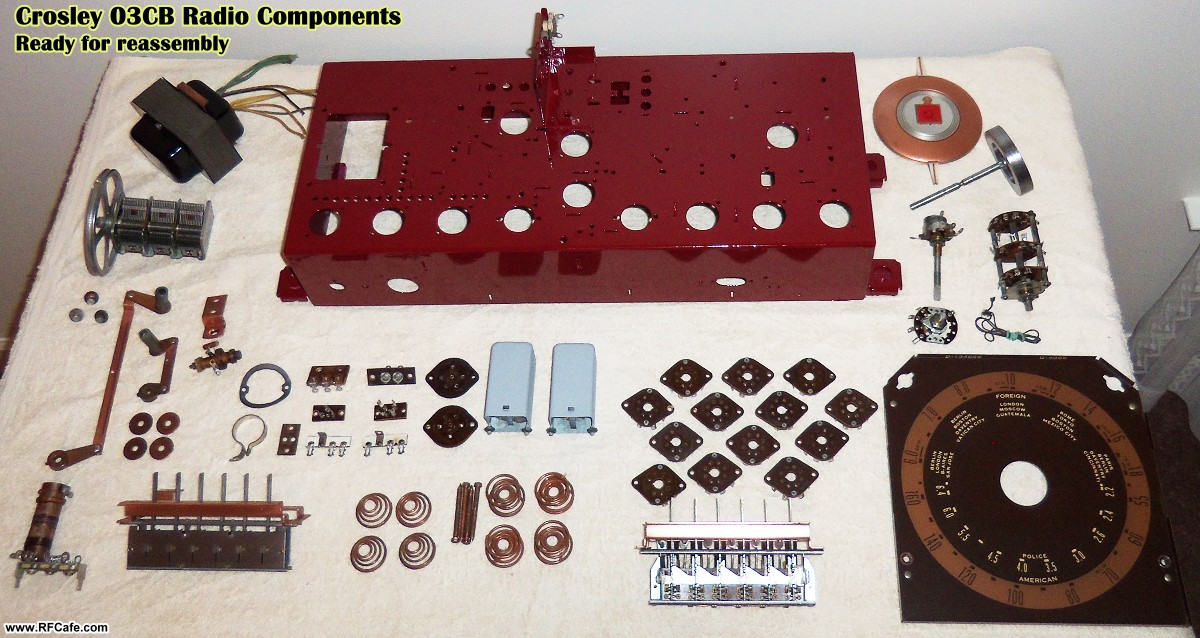
promised, here are the first of the electronics chassis restoration photos. It was
decided from the beginning that the chassis would be stripped of all its components
so that the metal box could be completely sanded and re-painted. That involved not
just unsoldering all the individual components, but also drilling out the rivets
that secured the tube sockets and solder terminals. My plan was/is to someday rebuild
the original circuitry, but because I have so many other projects
(both electronic and woodworking) in the works and
in the queue, for now I am just going to re-install all the major hardware and wait
until later to solder back in all the resistors, inductors, and capacitors - all
of which will be newly manufactured components rather than trying to rehabilitate
the originals. See the bottom of this page for some 'before' photos. As
promised, here are the first of the electronics chassis restoration photos. It was
decided from the beginning that the chassis would be stripped of all its components
so that the metal box could be completely sanded and re-painted. That involved not
just unsoldering all the individual components, but also drilling out the rivets
that secured the tube sockets and solder terminals. My plan was/is to someday rebuild
the original circuitry, but because I have so many other projects
(both electronic and woodworking) in the works and
in the queue, for now I am just going to re-install all the major hardware and wait
until later to solder back in all the resistors, inductors, and capacitors - all
of which will be newly manufactured components rather than trying to rehabilitate
the originals. See the bottom of this page for some 'before' photos.
Dark red paint was on the outside surface and a copper type of plating was on
the inside of the steel metal chassis. I decided to sand, prime, and paint all the
surfaces with dark red enamel. When the discrete components eventually get reinstalled,
the paint will need to be scraped off areas where ground attachments are soldered,
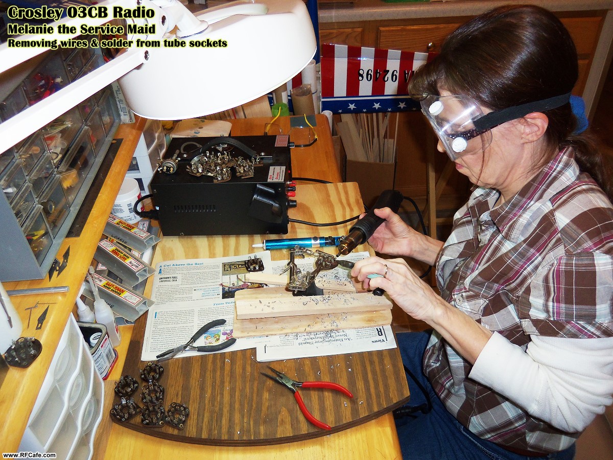
but that will not present a problem. Melanie volunteered to perform the tedious
task of removing the solder and component wire lead stubs from all the tube sockets,
rotary switches, potentiometers, and other components. I titled the picture below
of her doing the chore, "Melanie the Service Maid," a la the "Sally the Service Maid" series that appeared in World War II
era editions of Radio Craft magazine. All the parts were then scrubbed
with acetone and a wire brush, then sprayed with a light coat of clear lacquer for
preservation. As with the chassis ground tabs, the other solderable areas will be
scraped later to facilitate soldering.
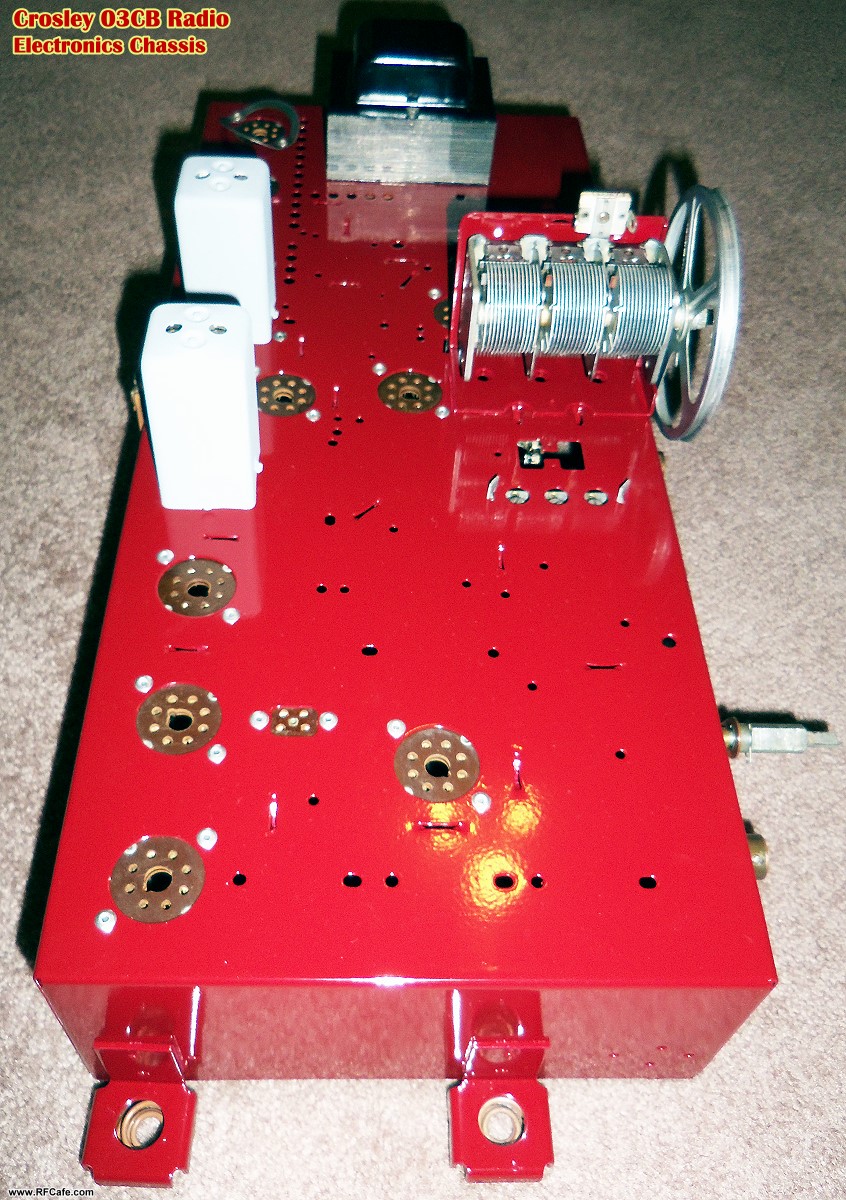
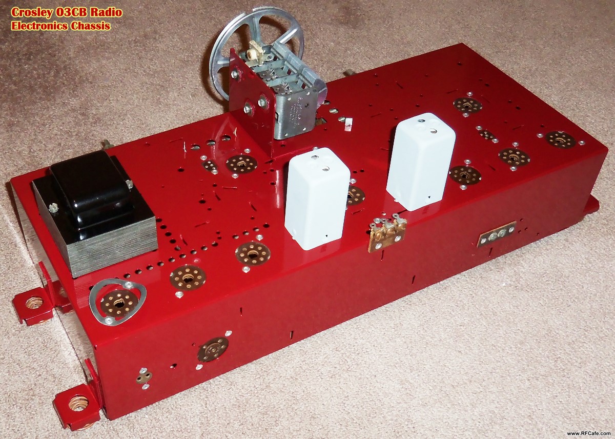
After allowing the paint to dry for about a week, all the tube sockets and other
items were pop riveted back into place. The cleaned-up adjustable capacitor tuner,
tuning coils, rotary switches, a very heavy transformer (with
re-painted metal shields) and other hardware were all bolted back in place.
Wow, do they ever look good! I'll bet the ladies who put them in 75 years ago at
the factory in Cincinnati, Ohio, would be happy to know that someone cared enough
about their work to find it worthy of restoring and preserving. The dial plate,
pushbutton station changer assemblies, and tubes will be reinstalled after the wood
console is ready, which hopefully will be by the middle of next week
(the 4th and final coat of polyurethane is drying now).
It might seem a bit cheesy, but for now I am going to re-wire all the 6.3 V
tube heater pins and the front panel light sockets to get everything to glow when
the power switch is turned on - just for the ambience. I'm even considering cutting
off the receptacle end of an extension power cord and plugging a modern radio into
it so that a radio will play when the Crosley's power switch is turned on. Hey,
don't you roll your eyes at me ! :-)
The next series of photos will be with everything back together.
|

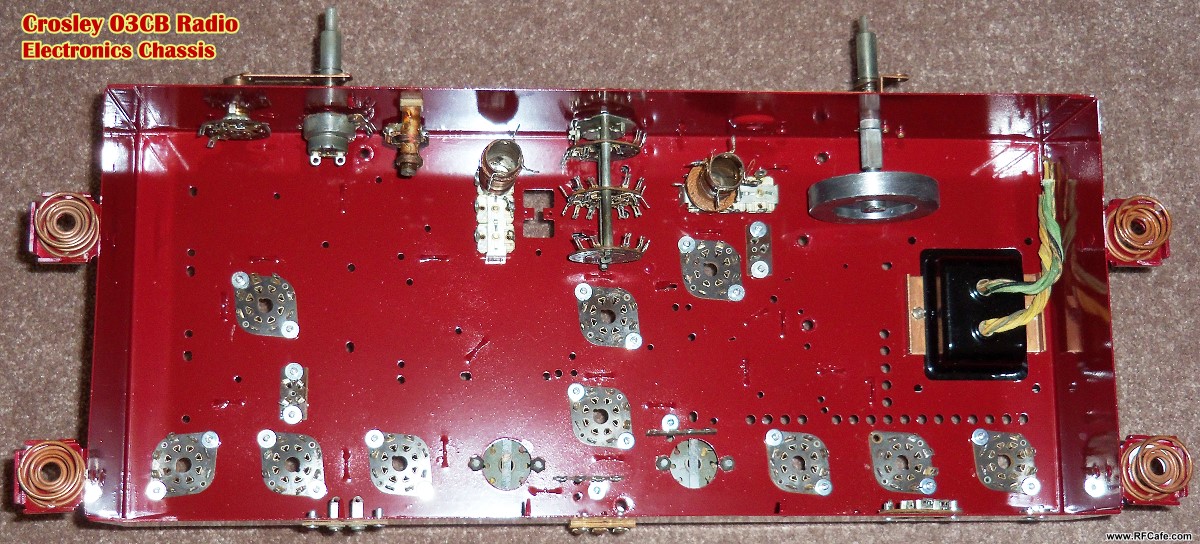
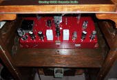
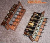
Crosley03CB
Refurbished electronics chassis components

Crosley03CB
Electronics chassis components mounted (top)
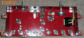
Crosley03CB
Electronics chassis components mounted (bottom)
|

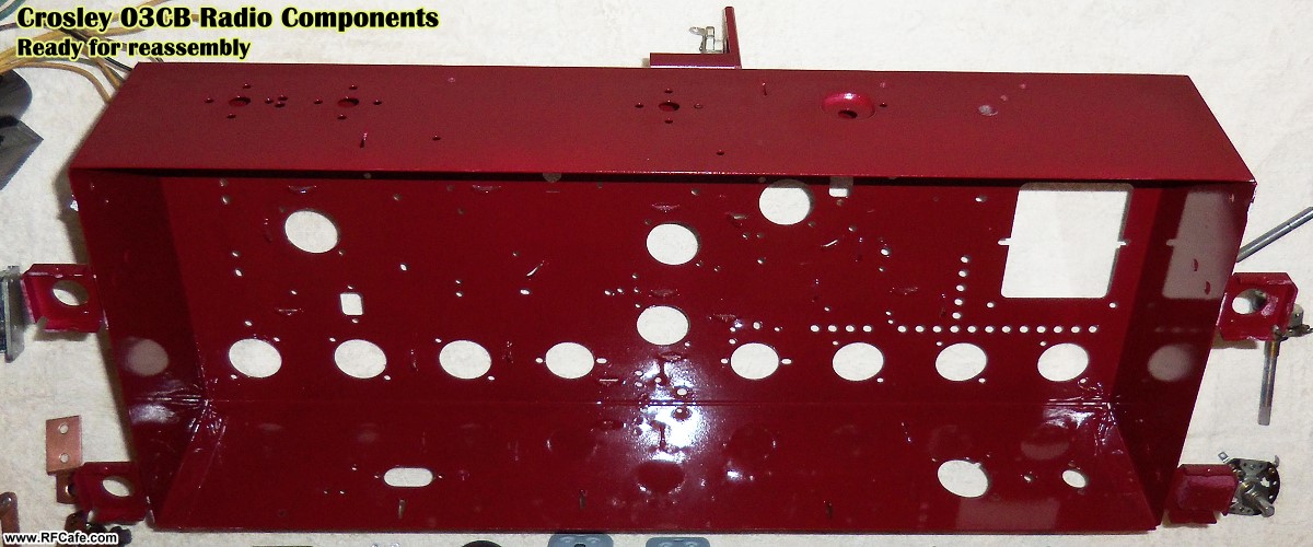
Crosley03CB
Freshly painted metal chassis

Crosley03CB
Electronics chassis components mounted (top)

Crosley03CB
Electronics chassis components mounted (top)
|
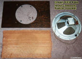
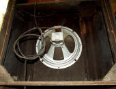
Crosley03CB
Speaker assembly
Crosley03CB
'Melanie the Service Maid' removing solder and
lead clippings from tube sockets
Crosley03CB
Pushbutton tone & tuning assemblies
|
November 17, 2014 Update: A couple months ago I finally picked up on
the restoration of my circa 1942 Crosley 03CB console radio. All of the hardware
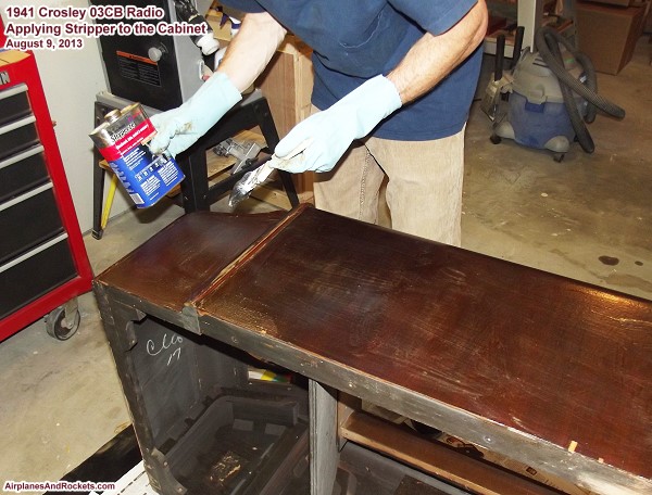
was removed from the wooden console in preparation for restoration. Paint stripper
was used to remove the bulk of the original finish, and then sandpaper along with
a lot of muscle power took care of the rough and final sanding. As can be seen on
some of the "before" photos below, there were many places where the walnut veneer
had delaminated and other where small areas where pieces had broken off. I obtained
some replacement wood from a vendor on eBay and spliced in the missing areas. Delaminations
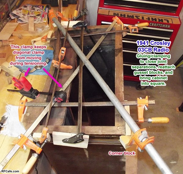
were glued back in place using
Elmer's Carpenter's Wood Glue. A few of the wood corner gussets
needed to be re-glued as well, and some of the solid wood frame pieces had glue
smeared into the joints and then clamped. 80 grit sandpaper leveled off the really
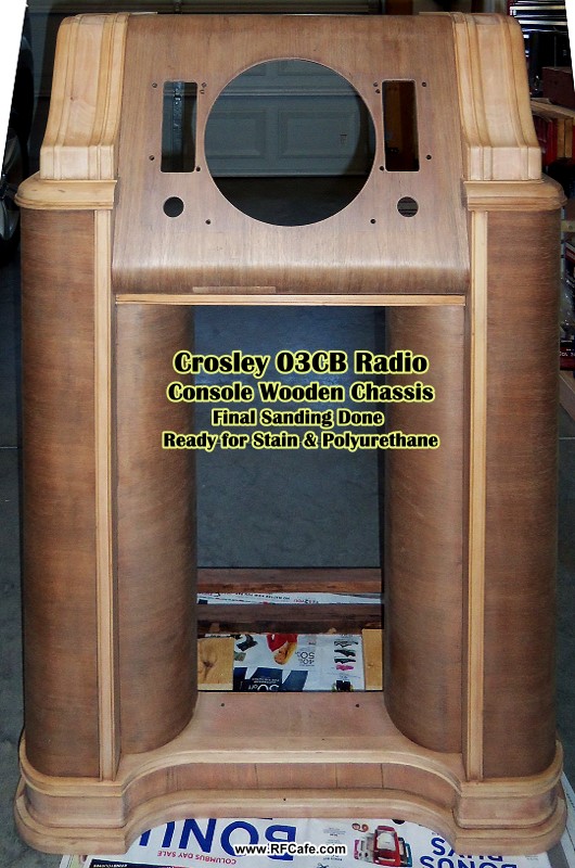
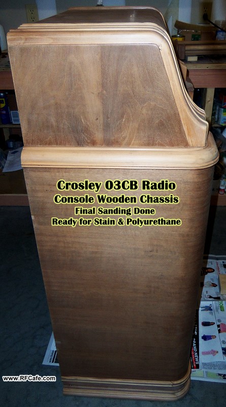
out of alignment areas, and 220 grit was used to prepare everything for stain and
polyurethane.
A light wiping of a walnut colored stain helped even out the coloring, with some
darker stain applied to patch pieces to bring them in color alignment with the original
wood. Two base coats of Minwax polyurethane were applied, with 220 grit sanding
in-between. I replicated the original information label that was on the original
chassis and glued it inside where the original was. A third coat of polyurethane
went on, including over the label. A final sanding with 320 grit sandpaper smoothed
out the foundation prior to applying the final coat of polyurethane using a foam
brush. I have found that a foam brush (or unused bristled brush) is best for at
least the final coat of polyurethane because it will not deposit any small pieces
of crap (technical term for bits of solid contaminant) in the finish. Be sure to
strain the final amount of polyurethane prior to application to eliminate all traces
of crap. Also, absolutely essential to obtaining a smooth, crap-free finish is to
thoroughly vacuum, blow off with an air hose, and then wipe all surfaces with a
tack rag between every coat.
Coming very soon: Photos of the electronics chassis restoration process.
|


Crosley03CB
Stripping console finish

Crosley03CB
Console front - ready for stain
|

Crosley03CB
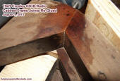
Squaring console frame

Crosley03CB
Console side - ready for stain

Crosley03CB
Console side - after staining
Crosley03CB
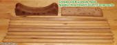
Speaker grille pieces
Crosley03CB
Obtaining curve for veneer replacement piece
|
Crosley03CB
Replacement walnut veneer glued and clamped
in place
Crosley03CB
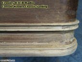
Console lower trim sanded
Crosley03CB
Re-gluing console joints

Crosley 03CB
Console upper trim sanded
Crosley03CB
Console front - after staining
|
August 3, 2013 Update: Read about my experience
electroplating copper back
onto some of the mounting hardware.
 June 22, 2013 Update: After
searching occasionally for many years for another Crosley 03CB radio in a location
close enough to drive to, I finally saw one on Craigslist in Harrisburg, PA, about
300 miles from my home in Erie, PA. Melanie and I picked it up yesterday. It needs
- and will receive - a total restoration for both the cabinet and the electronics,
but it appears to be in better condition that my first pre-restored Crosley 03CB.
This radio is Chassis #95. June 22, 2013 Update: After
searching occasionally for many years for another Crosley 03CB radio in a location
close enough to drive to, I finally saw one on Craigslist in Harrisburg, PA, about
300 miles from my home in Erie, PA. Melanie and I picked it up yesterday. It needs
- and will receive - a total restoration for both the cabinet and the electronics,
but it appears to be in better condition that my first pre-restored Crosley 03CB.
This radio is Chassis #95.
If you look at the photo below of the first radio (the one with my kids and father-in-law
sitting next to it), you will notice that the tuning dial has no cover over it.
I never knew there was supposed to be a glass bezel in front of the dial. Back in
the 1980s when I restored that radio, the Internet was still Darpanet and 'normal'
people did not have access, so research was much more difficult. I could not even
find SAMS Photofacts for it in order to work on the electronics. Fortunately, I
was now able to buy a high resolution scan of the original Crosley documentation
for a mere $9.95 in PDF format (AntiqueRadioSchematics.org).
Here are a few initial photos of how the radio looked when I picked it up. A
thorough documenting of the restoration process will be posted here over time. Before
doing any of the major work, I need to complete the
grandmother clock I've been working on for the last couple years.
It was built from scratch using hickory wood from the local lumber mill. I'm in
the final sanding phase as this is being written, so the stain and polyurethane
will come soon. Then, finally, the clockworks will be mounted inside (it's already
been test-fitted), glass panels installed, and the clock will assume an esteemed
spot in the living room.
|

Crosley03CB
Console Front View

Crosley03CB
Electronics Chassis Top

Crosley03CB
Console Side View
|

Crosley03CB
Console Rear View
Crosley03CB
Tuning Dial & Buttons

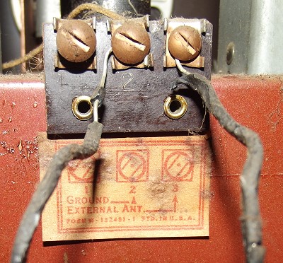
Crosley03CB
Antenna Connection Terminal
|
 Crosley 03CB
Console
Top View

Crosley03CB
Electronics Chassis Rear
Crosley03CB
Speaker Rear

Crosley03CB
Nomenclature Label
|
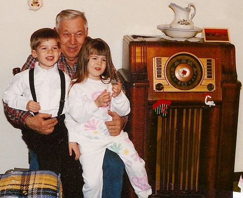
This 1941* Crosley floor console radio model 03CB was given to me as a Christmas
present in 1983 by my wife, Melanie. It was found by my sister, Gayle, and her husband,
Mike, in a barn on Kent Island on the Eastern Shore of Maryland. It sported a couple
shortwave bands and AM (no FM in those days). Unfortunately, I did not take any
detailed pictures of the unit, so the best I could come up with is this shot of
my two children (Philip & Sally) sitting with my father-in-law, Marlet Goodwin,
on Christmas day of 1990.
Its original finish was peeling off, and all the metal parts - the dial and trim
plates, electronics chassis, etc., was rusting. It sat in our house for a couple
years and then I tackled the refinishing project. Every bit of of the stain and
shellac was removed from the case, and paint from the metal parts, using naval jelly
(the good, caustic pink stuff). Hours of scraping, filling and sanding took care
of the wood, and then a Minwax stain was applied, with a top coat of a few coats
of Deft lacquer. The dial was carefully cleaned and lacquered. The dial trim plate
was primed and painted gold (the original color). I removed all the tube and primed
and painted the chassis gray (its original color). All the paper capacitors were
replaced, and the tubes were tested on a portable tube tester that had been given
to me by überengineer Jim Wilson. Only a couple needed replacing. Those were the
days before eBay and the Internet, so finding replacements took enlisting the help
of Ham friend who found them at a Hamfest. The antenna was a solid rectangular coil
that ran around the rear outside edge of the entire chassis.
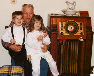
Marlet Goodwin (aka 'Grandpa") with Philip & Sally Blattenberger
After doing a good visual and continuity check of the electronics, I plugged
the radio into the wall. No smoke - that was a good start. A beautiful warm glow
appeared at the base of all the tubes, and before long there was a welcoming 60 Hz
hum coming through the huge electromagnetic speaker (no permanent magnet). I turned
the dial and, voila!, the local AM stations came in clear as a bell (well, as a
bell with a 60 Hz hum). The hum was eventually tamed by adding a couple caps
across the coil. It probably killed some of the bass, but who would notice on AM?
I pushed the "Japan" button and picked up some foreign station, but it definitely
was not from Japan. Similarly, other far away broadcasts were received on the other
bands, but I cannot recall the details.
Melanie and I gave the radio to her sister as a wedding present in 1993, since
her sister's home was decorated in a Victorian theme. It has since, shall we say,
"moved on," and I now have no idea where it resides. Oh well, that's the risk I
took in gifting it. Here are a few of my other
projects.
* I originally had 1926 as the year since I remember seeing the date on
a label inside the radio, but research has shown that it is most likely a 1941 model.
The 1926 date was probably for one of the patents listed.
Crosley Radios, Cars, Appliances, & Proximity Fuses
  If you have any interest in vintage radios,
you undoubtedly are familiar with Crosley products. They were very different from today's
Crosley products in terms
of quality. My experience with
Crosley
was while restoring a 1941 console (floor) model that was given to me by my sister.
It was constructed of solid wood and a nice mahogany laminate. The face plate, dial,
and knobs were heavy gauge metal. Following the success of their radios, If you have any interest in vintage radios,
you undoubtedly are familiar with Crosley products. They were very different from today's
Crosley products in terms
of quality. My experience with
Crosley
was while restoring a 1941 console (floor) model that was given to me by my sister.
It was constructed of solid wood and a nice mahogany laminate. The face plate, dial,
and knobs were heavy gauge metal. Following the success of their radios,
 Crosley ventured into the
automobile market from 1939
through 1952. Crosley ventured into the
automobile market from 1939
through 1952.  Little known even amongst Crosley fans is
that they built proximity fuses during World War II. "Crosley's involvement
began in late October 1941 when they were contacted by the Bureau of Ordnance and
told that they would be contacted later that month concerning a 'top secret, top
priority' project." A Crosley VT (variable time) fuse was credited with the downing
its first Japanese dive bomber in 1953. The Brits used them against German V-1 Buzz
Bombs. Thanks to RF Cafe visitor Kevin A. for the tip. Little known even amongst Crosley fans is
that they built proximity fuses during World War II. "Crosley's involvement
began in late October 1941 when they were contacted by the Bureau of Ordnance and
told that they would be contacted later that month concerning a 'top secret, top
priority' project." A Crosley VT (variable time) fuse was credited with the downing
its first Japanese dive bomber in 1953. The Brits used them against German V-1 Buzz
Bombs. Thanks to RF Cafe visitor Kevin A. for the tip.
Related Pages:
- Crosley 03CB Floor Console Radio by
Adam Guha - 1941 Crosley
03CB Floor Console Radio Restoration Project -
Tesslor R-601S Vacuum Tube Radio Teardown -
Tesslor R-601S Retro Vacuum Tube AM/FM Radio w/Bluetooth 3.0 Modification
- Crosley 03CA Floor Console Radio for Sale
- 1941 Crosley Model 03CB Radio Photos (Tim
O.) - Radio &
Electronics Restoration Projects -
Vintage Ads
with Science / Technology Themes -
Vintage Magazine Ads
from Duke University's Ad*Access Website -
Vintage Radio Control
Systems
Posted June 22, 2013
|