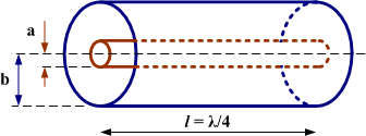
Quarter-wave (λ/4-wave) coaxial resonators are constructed by shorting the center conductor of a coaxial cable
to the shield at the far end of the circuit. The length of the cable is exactly λ/4 at the desired resonant frequency.
A short circuit is transformed to an open circuit a quarter wavelength away, so when the λ/4-wave coaxial resonator
is part of an oscillator circuit, it electrically is not even present (Z~∞); however, whenever the frequency of
the oscillator attempts to go above or below the resonator's center frequency (due to load changes, temperature
changes, etc.), the λ/4-wave section looks like a low impedance that works to attenuate other frequency components.
It acts like a parallel tuned L/C tank circuit. The advantage of a λ/4-wave coaxial resonator over a tuned L/C
tank circuit is the much higher quality factor, "Q."
Coaxial resonators are often made from sections of normal coaxial cable (both flexible and semi-rigid), but
many form factors are available that are manufactured for specific frequencies and mount on printed circuit boards,
or have coaxial connectors installed on both ends. Amateur radio hobbyists often use λ/4-wave resonators to filter
(trap) interference outside the working band of the radio operation. The nice thing about λ/4-wave trap it that
is can be connected inline with the antenna feed cable using a simple "T" adapter (remember, it is effectively
not even there at the center frequency).
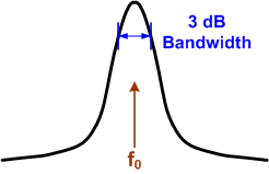
Quality factor of a λ/4-wave coaxial resonator is determined by the ratio of the center frequency to the 3
dB power bandwidth, as shown in the figure below. A set of equations is then presented for calculating the necessary
λ/4-wave coaxial resonator parameters.

Quality Factor (Q) of a λ/4-Wave Coaxial Resonator

Dimension Reference for λ/4-Wave Coaxial Resonator Equations


 |
Qc
Qcc Qd Q a b f μ σ εr n
Z0 Zopt |
= conductor contribution
to unloaded Q = conductor contribution to unloaded Q for copper conductors with optimum
b/a ratio of 3.59112 = dielectric contribution to unloaded Q = unloaded quality factor of a λ/4-wave
resonator, including conductor and dielectric losses = outside radius of inner conductor
(m) = inside radius of outer shield (m) = resonant frequency (Hz) = permeability of the conductor
(H/m) = conductivity of the conductor (mho/m) = relative dielectric constant between a and b = resonator
mode (# of 1/4 wavelengths at resonance) = characteristic impedance of coaxial structure (Ω) = characteristic
impedance that yields the highest theoretical value of Q (b/a = 3.59112) λ |
Note: These are commonly available equations; my source was Vizmuller
Related Pages on RF Cafe
- Coaxial Cable
Specifications
- Capacitor Dielectrics & Descriptions
- Dielectric Constant, Strength, &
Loss Tangent
- Conductor Bulk Resistivity & Skin
Depths
- Coaxial Cable Equations
-
Coaxial Cable Specifications
-
Coaxial Cable Vendors
- Coaxial Resonator
- Skin Depth Calculator
-
Coaxial Connector Usage Chart


