|
June 1955 Popular Electronics
 Table of
Contents Table of
Contents
Wax nostalgic about and learn from the history of early electronics. See articles
from
Popular Electronics,
published October 1954 - April 1985. All copyrights are hereby acknowledged.
|
Here is a short tutorial
on resistor-capacitor (R−C) combinations and the time constants created by their
combinations. It's pretty basic stuff, but there are new people coming into the
field of electronics all the time so it is worth posting. Discussed are coupling
circuits, filter networks, differentiators, and time-delay circuits. The "After
Class" feature is a series run by Popular Electronics magazine in the 1950s
and 1960s. As with this installment, "After Class" presented topics on electricity
and magnetism that served not just as new material for beginners, but was a good
review even for seasoned practitioners of the craft. A complete list of all the
"After Class" articles I have posted is listed below.
After Class: Resistor and Capacitor Combinations
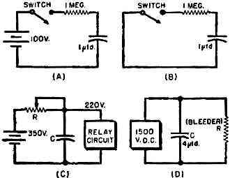
Example RC circuits.
Resistor-capacitor combinations (R-C) are given many bewildering names to distinguish
one function from another. Classifications like coupling circuits, filter networks,
differentiators, time-delay circuits and so on are just a few samples of these groupings.
No wonder the novice often throws up his hands in discouragement at the seeming
complexity of electronics. Yet, regardless of function or classification, every
R-C combination may be shown to be a simple circuit in which a capacitor charges
or discharges through a resistor over a given period of time. This action is merely
applied in different ways to achieve various special results.
If a capacitor is connected through a resistor to a source of d.c., as illustrated
in Diagram A (below), it does not reach full charge the instant that the switch
is closed. A definite, easily calculated time is required for this process. All
that one needs to know is the resistance in megohms and the capacitance in microfarads;
these values are then substituted in the simple expression given below and the time
required reach to full charge (actually about 99.6% of full charge) may be found
by simple arithmetic:
 Time for full charge (seconds) Time for full charge (seconds)
= 5 x R (meg.) x C (μfd.)
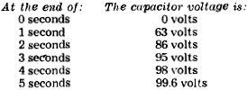
Consider a circuit like that of Diagram A in which a 1-μfd. capacitor is being
charged through a 1-megohm resistor by a 100-volt d.c. source. If the voltage across
the capacitor is measured after each second elapses from the time of closing the
switch, results like those in the table to the right are obtained.
Notice how the voltage at first rises very rapidly (63 volts during the first
second). As time passes, the voltage changes during successive seconds become smaller
and smaller until, during the fifth second, the increase is less than two volts.
This is typical of the capacitor charging process.
Should the charging battery now be replaced by a connecting wire (Diagram B),
the capacitor behaves like a voltage source and promptly starts sending a current
through the resistor. Again, at the end of a five-second interval, the discharging
process is practically complete, indicating that time for charge and discharge in
a particular circuit is the same.
See how the formula works out with somewhat different values, say, 15,000 ohms
of resistance and 0.01 μfd. of capacitance. The time for full charge is:
T = 5 x R(meg.) x C(μfd.)
= 5 x 0.015 x 0.01= 0.00075 second
= 750 microseconds
The microsecond, abbreviated μsec., is often a more convenient unit especially
for the expression of very short intervals.
A very important application of these ideas is found in "bleeder" systems used
on transmitter power supplies. During operation, the filter capacitors are charged
to the full voltage of the power supply, often 1500 volts or more. When the supply
is shut down, these capacitors retain a lethal charge unless they are "bled" or
drained (Diagram D). The resistance of the bleeder must neither be too low nor too
high. Assume that the lowest safe value of the bleeder to avoid excessive current
consumption is 25,000 ohms, that the power supply voltage is 1500 volts, and that
the capacitance to be drained is 4 μfd. How long will it take to discharge the
capacitors fully?
T (sec.) = 5 x R(meg.) x C(μfd.)
= 5 x 0.025 x 4
= 0.5 or 1/2 second
This time for discharging the capacitors is short enough to remove the hazard
of accidental "discharge" shock.
The charge and discharge equations are more often expressed as follows to avoid
the use of the number "5" before the R x C:
1. Time required to charge a capacitor to 63% of the source voltage (seconds)
= R(meg.) x C(μfd.)
2. Time required to discharge a capacitor to 37% of its original full charge
= R(meg.) x C(μfd.)
For example, suppose a given capacitor is charged to 350 volts. Its capacitance
is 1 μfd. and it is to discharge through a 1-megohm resistor. What will be its
voltage after discharging for 1 second?
Time to discharge to 37% of original voltage = R x C = 1 x 1= 1 second
Thus, at the end of 1 second, the capacitor will have discharged to 37% of 350
volts, or approximately 130 volts.
To show how these ideas may be used in building a timer, try this one: a charging
capacitor is to trigger a relay circuit when it reaches 220 volts. The source voltage
is 350 volts, the time delay desired is 8 seconds, and a capacitor of 2 μfd.
is available for use (Diagram C). At what resistance should the variable resistor
(potentiometer R) be set to trigger the relay? Also, what standard value potentiometer
should be purchased?
T (sec.) for 63% full charge
= R(meg.) x C(μfd.)
8 =R x 2
R = 8/2 = 4 megohms
Since 0.63 x 350 = 220 volts, the capacitor will charge to this potential - the
triggering potential - with exactly this value of resistance. A 5-megohm commercial
potentiometer would do nicely.
The following quiz is intended as a self check. All of the questions can be answered
correctly if the foregoing text has been mastered. Answers appear at the bottom
of the page.
Quiz
1. Is it ever possible for any capacitor to charge instantaneously?
2. In using the equation for charge or discharge, what units should R and C be
expressed in?
3. If a charging resistance is 500,000 ohms, what figure should it be changed
to before substituting in the equation for charge time?
4. If a capacitor to be discharged has a value of 2500 μμfd., what value
should be used in the equation?
5. How much time in microseconds is required to charge a 0.001-μfd. capacitor
through a 50,000-ohm resistor fully?
6. If the resistance through which a 1000-μfd. capacitor is to discharge is
500 ohms, how long will the discharge process take?
7. If a filter capacitor of 10 μfd. is to discharge fully in 1/2 second, what
is the maximum size (resistance) of the bleeder?
8. A certain capacitor is to charge to full source voltage in 100 microseconds
through a 5000 ohm resistor. What capacitance should it have?
9. A capacitor of 1 μfd. discharges through a resistor of 1,000,000 ohms.
if it was originally charged to 1000 volts, what will be its voltage at the end
of 1 second?
110. A 10-μfd. capacitor charges through a 10-megohm resistor. How long will
it take to charge to 63% of the applied charging voltage?
"After Class" Topics
Quiz Answers - Capacitor Resistor (Questions on page 85)
1) No. All lead wires have a certain amount of resistance, even
though it may be small, and takes time to charge a capacitor though a resistance.
2) R in megohms, C in μfd.
3) 0.5 megohms.
4) 0.0025 μfd.
5) 250 microseconds.
6) 2.5 seconds.
7) 10,000 ohms.
8) 0.004 μfd.
9) 370 volts.
10) 1 minute and 40 seconds.
Posted December 22, 2023
(updated from original
post on 8/7/2019)
|