|
December 1954 Popular Electronics
 Table
of Contents Table
of Contents
Wax nostalgic about and learn from the history of early electronics. See articles
from
Popular Electronics,
published October 1954 - April 1985. All copyrights are hereby acknowledged.
|
Popular Electronics
magazine wanted to be all things to all people - hobbyists, technicians,
engineers, students, general public) as far as electronics goes.
From the very first edition in
October of 1954 (two prior to this one), they included
articles on circuit troubleshooting, electrical theory, Amateur
radio, DIY building projects, radio control systems for airplanes and boats,
product reviews, and much more. The first issue's "After Class" column was
"Series and Parallel Operation of Resistors" and the second issue was entitled
"Basics of Series and Parallel Circuitry." Over time, topics delved deeper into
various components and circuit configurations, then started back again with the
basics. Doing so was more necessary than today since back issues were not as
easily obtainable - either online or from a source like eBay.
After Class: Alternating Current Principles
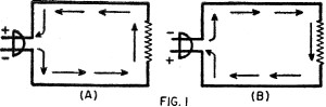
Fig. 1 - DC current flows in one direction.
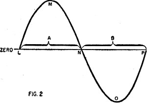
Fig. 2 - Sinewave
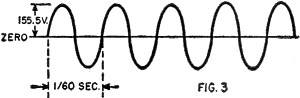
Fig. 3 - 60 Hz sinewave.
An alternating current is one which periodically reverses its direction. This
is illustrated in Fig. 1. At A, when the polarity of the line is as shown,
electrons flow through the circuit in the direction indicated by the arrows. A short
time later, the polarity of the power line reverses and the direction of current
also reverses as shown by the arrows in B of Fig. 1.
Usually the current changes gradually with time from maximum in one direction
to maximum in the other direction. This change can be represented by a drawing such
as shown in Fig. 2. This drawing or graph shows that the current rises from
zero at time L to its peak value at time M. The current then decreases until it
reaches zero again at time N. It now reverses direction and builds up until it reaches
its maximum value in the opposite direction at time O. The current then decreases
until it once more drops to zero at time P. The variation of current between time
L and time P is known as one cycle. The number of such cycles which occur in one
second is known as the frequency. For example, the usual power line frequency is
60 cycles-per-second; this means that one complete cycle will have a duration of
1/60 second. The frequencies used in radio and television broadcasting are much
higher than the power-line frequency and are usually specified either in kilocycles
(kc.) or megacycles (mc.). A kilocycle is equal to 1000 cycles, and a megacycle
is 1,000,000 cycles.
Since the instantaneous value of an alternating current or voltage varies continually,
there must be some agreed-upon way of specifying its value. Actually, there are
two commonly used ways of specifying this value: peak and r.m.s. The peak value
is the maximum value reached during the cycle. For example, the 110 volt power line
has a peak value of over 155.5 volts as shown in Fig. 3. The r.m.s. value of
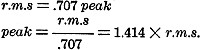
a sine wave alternating current or voltage is equal to .707 times the peak value.
The letters r.m.s. stand for root-mean-square, the name of the mathematical operation
by
which the factor .707 is derived. The relationship between peak and r.m.s. values
may be written:
Example:
What is the r.m.s. value of an alternating current whose peak value is 3 amperes?
Answer:
r.m.s. = .707 peak
r.m.s. = .707 X 3
r.m.s. = 2.121 amperes
Example:
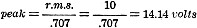
What is the peak value of an alternating voltage whose r.m.s. value is 10 volts?
Answer:
Unless otherwise stated, alternating volt-age or current is specified in r.m.s.
values. For example, when we speak of the 110- volt power line we mean 110 volts
r.m.s. Likewise a.c. values given on a circuit diagram are assumed to be r.m.s.
unless otherwise noted. Unless designed for specialized applications, a.c. meters
are calibrated to read r.m.s. values. The r.m.s. value of voltage or current is
also called the effective value, since it gives the number of volts or amperes of
d.c. which would produce the same effect, in heating, for example.
Depending upon the components of a circuit, the current and voltage may be either
in-phase or out-of-phase. When they are in-phase, current and voltage reach corresponding
peaks at the same instant and pass through zero at the same instant, as shown in
Fig. 4A. If the current either leads or lags the voltage, the two are said
to be out-of-phase. These conditions are illustrated in Figs. 4B and 4C. The amount
by which current and voltage are out-of-phase is known as the phase angle and is
usually specified in degrees (one complete cycle = 360°).
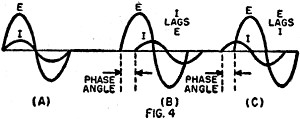
Fig. 4 - Leading and lagging phases.
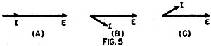
Fig. 5 - Phase vectors (phasors).
Phase angles are often indicated by means of drawings such as those in Fig. 5.
Here, arrows instead of sine waves are used to represent the current and voltage.
These arrows are known as vectors, and the drawing itself as a vector diagram. The
lengths of the vectors indicate the amounts of voltage and current. These are often
drawn on graph paper where each square represents a certain number of volts or amperes.
Vectors are considered to be pivoted in the center and rotating in a counter-clockwise
direction. The three vector diagrams in Fig. 5 present exactly the same information
as the three drawings of. Fig. 4. In A, the current and voltage are in phase.
In B, the current lags the voltage. In C, the current leads.
The following quiz is intended as a self-check. You should be able to answer
all of the questions correctly if you have mastered the foregoing text. The answers
appear on page 128.
1. What is the r.m.s. value of a sine wave having a peak of 300 volts?
(a) 425 volts; (b) 212.1 volts; (c) 42.5 volts
2. A frequency of 1500 kc, is equal to:
(a) 1.5 mc.; (b) 1.5 cycles; (c) 1,500,000 mc.
3. What is the peak value of a 220 volt r.m.s. power line?
(a) 311 volts; (b) 155 volts; (c) 110 volts
4. At a frequency of 400 cycles-per-second, the duration of each cycle is:
(a) 400 seconds; (b) .0025 second; (c) 250 seconds
5. If the frequency of an alternating current is increased but its peak value
remains the same, its r.m.s, value will:
(a) increase; (b) decrease; (c) remain the same
Vanishing Volts
The odd behavior of a common voltmeter when used to measure the plate potential
of an electron tube amplifier is very mystifying unless one remembers that the meter
itself is a part of the circuit being measured. This idea will be clarified by referring
to the schematic diagram of the resistance-capacitance coupled amplifier shown in
the diagram.
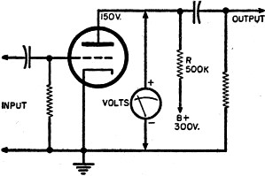
Fig. 6 - Capacitor-coupled amplifier stage.
If the amplifier is performing properly - and this we shall assume - it is fair
to anticipate a voltage drop of perhaps 150 volts in the plate load resistor, R.
This would leave 150 volts for the plate. A voltmeter, connected as shown in the
diagram, ought to read this voltage but, surprisingly, it will probably register
a great deal less - possibly as little as 10 or 15 volts. If your reaction to this
reading is to conclude that the meter is delinquent, forget it! You couldn't be
wronger!
But the fact remains that the plate voltage has vanished! Where?
The explanation involves two distinct considerations: first, the ordinary voltmeter
generally requires about 1 ma. of current through its coil to make it read full
scale; second, this additional current is being drawn through a relatively high
resistance, that of the plate load resistor R.
With the meter disconnected from the circuit, the voltage drop across R is, as
mentioned, about 150 volts. The fall of potential results from the flow of plate
current through the resistor which, of course, is in series with the tube plate
circuit. Just as soon as the meter is connected from plate to ground it, too, draws
current to make its needle deflect, producing an additional voltage drop which may
be quite high. On the other hand, the decrease in plate voltage will produce some
decrease in plate current.
For example, let us suppose that our tube is the triode section of a 12SQ7GT,
with -1.5 volts grid leak bias. The plate current will be approximately 0.31 milliampere,
the voltage drop across R will be 0.00031 x 500,- 000, or 155 volts, and the plate-to-cathode
voltage will be 145 volts. Now suppose we connect a 1000 ohms-per-volt meter, set
to its 250-volt range, between the plate and cathode of the tube. The meter reading
would be approximately 94 volts. With this plate voltage and the same bias as before,
the tube would draw only 0.036 milliampere. The meter, which draws 1 milliampere
for a full-scale reading of 250 volts, would draw 94/250 or 0.376 milliampere. The
total current through R would be 0.376 plus 0.036, or 0.412 milliampere. The total
drop across R is 0.000412 x 500,000, or 206 volts. 300 minus 206 equals 94 volts.
If we set the meter on its 100-volt range, the reading would be approximately
50 volts. With this plate voltage, and bias as before, plate current of the tube
would be practically cut off, and meter current would be 50/100, or 0.50 milliampere,
which is enough to account for the entire 250·volt drop across R. Similarly, on
the 50-volt range, the reading would be approximately 27 volts, and on the 25-volt
range, 14 volts. The lower the range we use, the less the resistance of the meter
will be, the more current will flow through R, and the greater the voltage drop
across R will be.
Colloquially, this is known as "loading down" the circuit. The only way to avoid
it is to take all such measurements with a good vacuum-tube voltmeter (v.t.v.m.),
an instrument which draws practically no current at all through the plate load.
Starting Fluorescents
Modern fluorescent lighting tube emits light as a result of the excitation received
by its inner, chemical coating from the ionized gas contained within it. A somewhat
unfortunate characteristic of ionization is that the striking potential required
is much greater than the operating potential. Ordinary household fluorescent lighting
fixtures must incorporate a starting scheme which applies a sudden surge of high
voltage across the tube, - voltage which is removed once the arc has been struck.
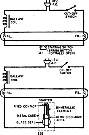
Fig. 7 - Fluorescent lamp starter circuit.
Two methods for obtaining starting potentials are now in common use. The first,
generally found in desk and floor lamps, is a manual starting system requiring a
spring push-button (see diagram A). A ballast coil having a relatively high inductive
reactance is in series with a filament at each end of the tube and with the starting
switch. When the switch is closed, current flows through the series circuit causing
the filaments to heat and emit electrons but no arc discharge can occur between
them because the closed switch keeps the potential difference quite low. When the
button is released, however, the usual inductive voltage kick-back appears across
the tube of sufficiently large magnitude to initiate the discharge. Once started,
the arc continues since the voltage across the tube is in the region of 100 volts.
To extinguish the light, a separate series switch is incorporated in the line to
open the circuit.
Ceiling fixtures use an automatic starting method involving plug-in starters.
A starter is a rather interesting combination of glow-discharge tube and a bi-metallic
element. The latter is made by bonding together two dissimilar metals having widely
different coefficients of expansion; when heated, such an element bends, with the
metal having the lower coefficient on the inside of the curve. In diagram (B), the
bi-metallic element is shown straight and upright; application of heat, however,
would cause it to bend toward the contact point.
When the unit is switched on, a glow discharge begins in the area indicated in
the diagram. The heat from the discharge is conducted to the bi-metallic element,
causing it to bend toward the contact point and close the circuit. Now the filaments
heat up since a complete circuit through the filaments has been established through
the ballast coil, but the little glow discharge ceases since the contact between
the bi-metallic element and the point has short-circuited the discharge path. The
bent bi-opening, the same inductive kick-back encountered in the manual case appears
to initiate the discharge arc. Once the lamp discharge starts, the voltage across
the starter is not high enough to restrike the glow and it remains out.
Posted October 14, 2020
(updated from original post on 7/25/2011)
"After Class" Topics
|