The Useful Decibel
|
|
You can tell by the number of articles in electronics magazines (see list at the bottom) that a lot of people struggled with the concept of decibels (dB). Probably the issue was more converting between linear units and decibel units, since exponents and logarithms are involved. Teaching someone to add and subtract decibels, or to multiply and divide, respectively, linear units is relatively simple, and is not confusing. For some people, converting power levels from watts (or milliwatts) to decibels can become a rote operation; no real understanding of the concepts is required, but throw in a factor of two for voltage to power (and vice versa), and the eyeballs are likely to roll back in the head ;-) Mr. Eric Leslie did his part to try to ease the pain in this "The Useful Decibel" article in the February 1968 issue of Radio−Electronics magazine. The Useful Decibel
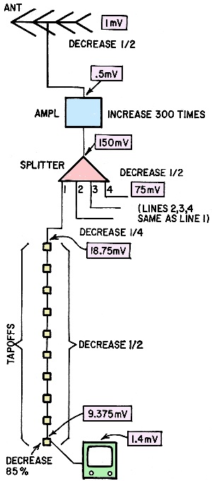
Fig. 1 - Functional diagram of typical MATV system, with signal levels in volts. Boxed figures are absolute values. Everywhere in electronics you find dB's - now learn them the painless way - without logarithms! By Eric Leslie Much nonsense, and worse - a lot of incomprehensible sense - has been written about the decibel, probably the most useful unit of measurement in elec-tronics. Yet in spite of that usefulness, too many technicians don't understand it. Why? Because most articles on the how and why of the decibel do more talking about logarithms than about decibels. That's fine, if you know logs. But if you don't, you have to learn logarithms and decibels, both at the same time. Nonlinear measurement How did the decibel come about? It was devised to measure nonlinear quantities. Did you know your ear does not have linear response to changes in sound volume? This is the reason you can hear a whisper across a quiet room, and also tolerate the blare of auto horns or the roar of a subway express train. Suppose you're listening to an amplifier with a wattmeter across the output. First you hear a 1-watt sound; then you crank up the gain to 2 watts. Does the speaker output sound twice as loud? No - it just sounds a little bit louder. You have to turn up the gain until you increase power output 10 times - to 10 watts - before you hear twice as much audio as you did at the 1-watt level. That, briefly, is the way your ear works.
Fig. 2 - Same system, using dB's. Again, signal levels are shown in boxes; gains and losses are not. See text for details. To describe this interesting system, the 10-to-1 power relationship was described mathematically and called a bel (in honor of Alexander Graham Bell). For more precise measurements, a tenth-of-a-bel unit - the decibel - was put in service. The decibel, then, is a measure of power ratio. It doesn't matter whether you increase or decrease the power - dB's work both way. Double the power, and you've increased it by 3 dB. Cut the power in half, and you've decreased it by 3 dB. Check this with the table. In column B find the ratio of power increase - 2.0. Opposite this point in column E you'll find 3 - the number of dB's of change. Decibels can also be used to measure the ratio between two voltages or between two currents. Since power equals voltage times current, though, voltage dB's come out differently than power dB's. Look at the chart again. Increase voltage by ratio of 2 (2.0 in column B) How many dB's of voltage increase? In column A you'll find 6. Here's why: Put 1 volt across a 1-ohm resistor. Since P = E2/R-or 12/1, power is 1 watt. Now increase voltage 3 dB. The chart says that a 3-dB voltage increase is a ratio of 1.4 to 1. So now what's the power? P = E2/R-or (1.4)2/1 or about 2 watts. Power has doubled - and according to the chart, that is 3 dB of power gain. (The same figures work for current, by the way.) How to use dB's Using dB's to measure changes in power, voltage or current makes difficult jobs easy. As an example, suppose you want to install a master antenna system in a large 40-unit apartment building. You make a diagram - like Fig. 1 - of the equipment. Then you figure how to get enough signal to each TV to furnish an acceptable picture. Assume you've got a 1-mV signal at the rooftop antenna, and you want no less than 1 mV at each receiver. From the antenna, the signal goes through coaxial cable. dropping to half the voltage (1/2 of 1 mV is 0.5 mV) by the time it arrives at the amplifier, where it's stepped up 300 times (300 times 0.5 mV is 150 mV). From the amplifier, the signal divides at a four-way splitter, and each output has half the voltage of the input (1/2 of 150 mV is 75 mV). Next there's more coax, dropping signal voltage to 1/4 (1/4 of 75 mV is 18.75 mV). The 10 receiver tapoffs in series cut the signal in half again (1/2 of 18.75 mV is 9.375 mV). The last receiver is isolated from the line by the tapoff, and this isolation drops the signal again - to perhaps 15% of the line signal (15% of 9.375 mV is about 1.4 MV). That's what the last receiver gets. If you like to multiply, as we've done, you're welcome to the method. There is an easier system, though - using decibels.
Decibel Table But first we've got to have a reference point. A dB figure is only a measure of the ratio between two power or voltage levels. It does not refer to an absolute value. In TV antenna work, 1 mV (or 1,000 μV) has become the reference point, because it is often the lowest signal that should be delivered to a receiver. Therefore, 1 mV is called "0 dBmV." Now look at Fig. 2, where 0 dBmV is beside the antenna, to show that's the signal available there. Coax drops the signal in half, and from the table you'll find that's a 6-dB loss, so write that down and subtract it from 0 dBmV, getting -6 dBmV. (The minus sign here indicates the signal is 6 dB below 0 dBmV.) Next convert the 300-times gain of the amplifier to the nearest value in the table, or 50 dB. Add +50 dB to -6 dBmV, getting +44 dBmV. (You can also do it by subtracting -6 dBmV from +50 dB; the result is the same. The plus sign here shows the signal is 44 dB above 0 dBmV.) Continue through the diagram, using the table to convert voltage increases or decreases to dB gain or loss. Eventually you'll find you have about +3 dBmV at the last receiver. From the chart, you see that's about 1.4 m V. Sure, you've had to do a lot of converting and using the table to work with dB's in this example-and it has been a nuisance. But you don't have to do it in practice. If manufacturers of amplifiers, splitters, tapoffs and cable told you only that their equipment would amplify a signal "300 times" or attenuate it "by 15%" you'd have to multiply and divide to layout a master antenna system. They don't do that, however. They give you dB gain or loss figures, and all you have to do is add and subtract them.
You determine the signal at the antenna is 0 dBmV. Since you also want 0 dBm V at the last receiver. It's obvious you need at least 47 dB of gain from the amplifier. You buy the nearest thing - a 50-dB unit. See how simple it is? Other dB uses Decibels aren't used solely in antenna work. Various reference levels are used in other areas of electronics. In broadcasting and recording studios, "0 dBm" is defined as 1 mW in 600 ohms of impedance. Years ago telephone companies and some radio stations used a 0-dBm reference point of 6 mW in 500 ohms. For higher-power applications, such things as "0 dBW" (1 watt) and "0 dBk" (1 kW) are used. There is even "0 dBV" (1 volt). Notice that 0 dBm means 1 mW only in 600 ohms. Impedance is defined because radio, television and recording studios have standardized on 600-ohm inputs, outputs and lines. A similar situation exists in master-antenna computations involving voltage. Hence, 0 dBm V means 1 mV (or 1,000 μV) across 75 ohms of impedance, since that's the common type of coax used. You can't use dB's to compare voltage differences unless the two voltages are across the same value of impedance. So you see, the dB is really not too difficult to work with. As a stranger, it's an unknown, perhaps incomprehensible element. Once you get to know it, the decibel will become a valuable tool in your electronics work. R-E
Related Pages: RF Cafe Decimal Tutorial
|
The Decibel Without Pain |
Using the Decibel | Decibel Tutorial:
dB and dBm vs. Gain and Milliwatts |
Versatile Voltage, Power, and Decibel Nomograms |
Decibel Level
vs. Decibel Gain |
A Decibel
Nomograph | The Decibel: AWG Wire
Size Rule of Thumb |
What is a Decibel? |
Understanding Decibels |
Decibels Without Logs |
The Useful Decibel | Decibels |
mW-to-dBm / dBm-to-mW Power Conversion |
NEETS: Decibel
Posted May 8, 2023 |
|


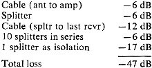 Assume you've made a plan of the apartment
building. From equipment catalogs, you obtain the following figures - all the losses
in your system:
Assume you've made a plan of the apartment
building. From equipment catalogs, you obtain the following figures - all the losses
in your system: