The Decibel Without Pain
|
|
Evidently - and understandably so - a lot of people in the electronics realm have a problem grasping the concept of a decibel as it pertains to voltage, current, power, et al. This 1960 Electronics World magazine "The Decibel Without Pain" article takes a stab at making it all clear. As the c1991 Teen Talk Barbie famously said, and in some cases like in this YouTube video still says, "Math class is tough." Believe it or not, that created quite a stir amongst feminists who, BTW, would have had no problem with Ken saying the same thing. The fact is, for many - probably most - people math class is tough. It was for me when I was in elementary school and junior high school. I nearly failed 9th grade algebra because for the life of me I could not get the hang of factoring polynomials. Being given the option of enrolling the the electrical vocational program for high school (grades 10 through 12) was my salvation. I loved working with electrical and electronic things, so being able to spend my days in prison (aka school) learning about residential, commercial, and industrial wiring, motors, and control circuits really motivated me. For some reason the same math that loomed over like the Grim Reaper whilst in a regular classroom setting somehow made sense when set to Ohm's law, Kirchhoff's law, Norton's law, magnetic and electric fields, and various sundry other practical applications. A few years later I breezed through math required in my USAF radar technician classes. A few years after that I managed to earn A's in nearly all my engineering level math classes (calculus, differential equations, linear algebra, complex numbers, etc.). The Decibel Without Pain
Practical hints on understanding and using these strange units. by someone who actually likes them. By now, we are all supposed to know that the decibel is a ratio between two quantities of power (or voltage, or current), not a quantity of power, voltage, or current itself. Thus we should not express any known electrical quantities as being simply "so many db" - unless we are in the advertising business. The copywriter may state, "Sudso is 20 per-cent faster" and get away with it before anyone asks, "Faster than what?" However, if a technician should state, "The power at this point is 30 db," someone will invariably want to know, "30 db above or below what?" In other words, there must be a reference level. Sometimes this level may be understood. In the telephone industry, for example, this reference is the input level to the switchboard from a subscriber line. Other levels throughout the system, expressed simply in db, are referred to this input, with the telephone engineer primarily concerned with the magnitude of the losses in the various portions of the path between the microphone of one telephone and the receiver of another.
Fig. 1 - Gains and losses in a transmission link are represented as shown to determine adequacy of signal level.
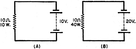
Fig. 2 - Two identical amplifiers connected (A) in series yield greater gain than they would (B) when in parallel. He is also interested in the gain in db of each amplifier in the chain that will restore the losses: what goes down must be brought back up again if Mom in New York is to hear Johnny's plea from camp for just another few dollars. In the detailed engineering of the circuit, he also becomes interested in the actual rather than relative power present at various points in the path, but that is a matter for db's twin brother, dbm, of whom more will be heard later. For the moment, let's consider only that the db is a ratio. An amplifier that produces 100 watts of output when 1 watt is fed into it is a 20-db amplifier. But so is another that produces 100 milliwatts out from 1 mw. in. From this comparison, we see that a 20-db amplifier is one that has a power gain of 100 times without regard to its actual power-handling capacity. What About Logs? The key to the whole db business, as many technicians unhappily acknowledge, is a working familiarity with logarithms. A great deal can be done in handling decibels without using logarithms, as will be noted later. However, those practical men who have been getting along without logs for years just don't realize what they are missing. Logs are very easy to use-they make multiplication and division less of a chore. In fact, logs literally turn multiplication into addition, and division into subtraction. This same great advantage is present in the use of db. Although a full discussion of the use of logs in general calculations will be avoided, it will be useful to review some facts concerning the logarithm to the base 10 before getting to the meat of the dog biscuits (db). The logarithm of a number is the power to which 10 must be raised to obtain that number. 100 is 10 squared (102), or 10 to the power of 2. Therefore, the power to which 10 must be raised to make 100 is 2; so the log of 100 is 2. To take another example, 2 is 10 to the power of 0.3 (to be precise, 0.3010, but who wants to be precise at a time like this?). To find this value, or to convert a number to a log or the reverse, either a table of logarithms or a slide rule may be used. To multiply several numbers together, we merely find their logs, add these together, and translate the new log thus obtained back to a number again. Thus, using the two logs we have already examined, let us multiply 100 x 100 x 100 x 2 x 2. With logarithms, this becomes 2 + 2 + 2 + 0.3 + 0.3, which quickly adds up to 6.6, the new logarithm. An antilog table or a slide rule tells us that the number of which is 6.6 is the logarithm is 4x10⁶, or 4,000,000. Now for tying up logarithms with decibels - in formula: db=10 log P1P2. "Which means?" as the straight man might say to his partner. "A decibel is ten times the log of the ratio between two power levels." "Why ten times?" "Because the bel, the first unit for measuring the relative level between two sounds, was too large to handle; so they chopped it into ten parts and called each a decibel (1/10 bel)." From the formula it is obvious that the db is logarithmic. In this fact lies many great advantages. Power ratios of millions to one can be expressed in simple numbers and vast products can be obtained by merely adding simple numbers together. If you think that this is rarely necessary, consider that a difference of only 60 db represents a power ratio of a million to one. Table 1 shows some of the easily remembered and frequently used power ratios, expressed as numerical ratios and in equivalent db. With these figures, many complicated calculations can be reduced to mental arithmetic. For example, whenever a given power level is multiplied by 10, we add 10 db (or, when it is divided by 10, subtract 10 db). To double any power, add 3 db. Since quadrupling a power is doubling it twice, this comes to 6 db (3+3) . Just by manipulating this table, many other ratios can be deduced. For example, to increase a power ratio 20 times, we must increase it 10 times (10 db) and then double it (3 db). Calculation will show that a power increase of 20 times is indeed a change of 10+3, or of 13 db. Other examples: To obtain 5 times a power, we can find 10 times that power and then halve it. In db, this would be +10-3, or +7 db. To increase by 50 times, we could increase by 10 times (+10 db) and then by 5 times (+7 db). The answer would be +17 db. To find 25 times (half of 50 times), we know that +17-3=+14 db. The Dbm
Fig. 3. Doubling voltage (B) applied across a circuit (A) also doubles current. Thus the power drop quadruples. The standard test tone used in the telephone industry is a 1000-cps signal with a power of 1 milliwatt. Since this is a convenient reference level, the term dbm, meaning "db with reference to 1 milliwatt," is now in widespread use. Since there is a specific reference point (1 milliwatt is always zero dbm) , any figure given in dbm is not a ratio. It is a definite quantity of power. Thus 1 watt (1000 mw.) can be written as +30 dbm; and 1 microwatt is -30 dbm. The dbm is very useful in system calculations. For example, let us take an imaginary u.h.f. link that must be set up. We have the following: 1. a 50-watt transmitter, 2. a receiver that requires an input of 50 microvolts of signal for efficient operation, 3. antenna feeders and connectors that entail a loss of 3 db at each end, 4. a required safety margin of 20 db to allow for fading, and 5. attenuation of the signal in the air path between transmitter and receiver shown to be 111 db. We draw a block diagram, as in Fig. 1. A 50-microvolt signal across the 50-ohm input impedance of our receiver tells us we need a power here of -73 dbm. This is another way of stating the receiver's sensitivity. The transmitter output, already given in watts, can be restated as +47 dbm. If we forget everything else (losses) in between transmitter and receiver, the ratio between the transmitter output and the power required at the receiver input is 120 db (not dbm) . This is the difference between transmitter output and receiver input, which is +47-(-73). This 120 db is called the system gain, and represents the maximum amount of attenuation that could be tolerated between transmitter and receiver without degrading performance. Now, on the debit side, we have: 3-db loss in the transmitter antenna feeder system, 111-db loss in the air path between these stations, and 3-db loss in the receiver antenna feeder system. These losses add up to -117 db. Thus, if the antennas used show unity gain (such as conventional dipoles), the system will work with 3 db to spare. However, we are looking for a 20-db safety margin to allow for fading. We must therefore use antennas that will give us a total gain of 17 db. Antennas at each end with a gain of 8.5 db each will do the trick. Now here is a point worth thinking about: If we left the unity-gain antenna at the transmitter and stacked two 8.5-db antennas at the receiver without losses, we would fall short of the gain requirement. We would get, not 17 db, but only 11.5 db! Let's consider this statement in a more familiar form - the case of the two amplifiers in Fig. 2. In series, with one amplifier multiplying the output of the other, the logarithmic increase is such that, expressed in db, we get twice the gain of one amplifier. In parallel (Fig. 2B), we only double the power. This (Table 1) is a gain of only 3 db over the use of one amplifier - or antenna. In the case of the amplifiers, this could easily be measured. To return to the dbm - it is so useful precisely because it indicates a definite power and yet can be manipulated in a logarithmic manner along with ordinary decibels. Transmitters, amplifiers, receivers, microphones, and loudspeakers can all be rated, as to sensitivity or output, in dbm, even though the impedance of each type of unit may be different. Other units similar to the dbm include dbw (referred to a level of 1 watt) , dbk (in reference to a kilowatt), and dbx, a unit of crosstalk between two circuits. There are also others. Voltage, Current Ratios So far, we have talked about the ratio between two powers. The ratio between two voltages, or between two currents, can also be expressed in db, where these are the quantities that are known-but the formula is different. This stems from the fact that, when you relate a given power to the voltage or current that is involved with it, the relationship is not linear. There is always a square involved (power, in watts, is I2R or E2/R). Again, we look at the matter in practical terms, with the help of Fig. 3. If we put a 10-ohm resistor across a 10-volt supply, 10 watts of power (Fig. 3A) will be dissipated in the resistor. If the voltage is doubled (Fig. 3B), the power in the resistor is not doubled - it is quadrupled. This is because, following the rule made public by Mr. Ohm, the current is doubled as well as the voltage. This brings us to another principle in the use of logarithms: to square any number, multiply its log by 2, then find the antilog of this product. Since a square is involved when we go from a power to a voltage or a current, we go back to our old db formula (Ugh! There he goes again!) for power ratios and multiply the logarithm by 2. Thus, for converting two voltages to a db ratio, the formula is db=20 log E1E2. However, a db is a db. If you compare two specific signals, the respective powers will be different from the respective voltages, but the db ratio will always be the same. The point may be further illustrated by reference to. Table 2, where the db equivalents for many voltage ratios are given. If the voltage across a given load is doubled, there is an increase of 6 db. Note that doubling the voltage across the load will have quadrupled the power. Thus a 4-time increase in power (Table 1) is a gain of 6 db. Reading a Db Meter
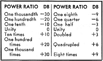
Table 1 - Common power ratios in db.
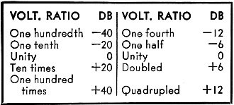
Table 2 - Common power ratios in db. A word of caution is necessary when reading db directly on a meter. The latter is actually a voltmeter, not a power meter, and is therefore calibrated for readings across a specific impedance. For relative readings, this is not much of a problem. For instance, if one should start out with a reading of +5 db across any circuit, and this reading should change to +3 db during tests across the same impedance, the change will always be a difference of 2 db. For reading dbm however, the impedance for which the meter was calibrated must be known. In most cases, this is "0 db-1 mw. in 600 ohms," usually printed on the meter face. However some older meters are calibrated to make zero db equal to 6 mw. in 500 ohms. In either case, this direct reading is obtained on one range, and direct readings on other ranges are corrected by adding or subtracting so many db, as specified by the manufacturer, where separate db scales are not used. If the impedance at which the db scales have been calibrated is in doubt, a check can be made against the voltage scales. For example, if 0.775 volt corresponds to zero db, the meter has been calibrated to the modern standard, and powers in a 600-ohm circuit can be read directly off the meter in dbm. Such readings can be made across other impedances too, simply by applying a correction factor. For example, let us suppose the meter is calibrated for 600 ohms. In reading across a 1200-ohm circuit, one would simply subtract 3 db from the scale reading to obtain the power in dbm. Across a 300-ohm circuit, add 3 db to the reading; across 150 ohms, add 6 db; and across 75 ohms, add 9 db. Correction factors can be worked out for any impedance. The important thing is to start using db wherever possible, even when they are not needed. The familiarity thus acquired will simplify matters when db becomes essential.
Related Pages: RF Cafe Decimal Tutorial
|
The Decibel Without Pain |
Using the Decibel | Decibel Tutorial:
dB and dBm vs. Gain and Milliwatts |
Versatile Voltage, Power, and Decibel Nomograms |
Decibel Level
vs. Decibel Gain |
A Decibel
Nomograph | The Decibel: AWG Wire
Size Rule of Thumb |
What is a Decibel? |
Understanding Decibels |
Decibels Without Logs |
The Useful Decibel | Decibels |
mW-to-dBm / dBm-to-mW Power Conversion |
NEETS: Decibel
Posted January 10, 2023 |
|