Frequency Modulation Fundamentals |
||
Frequency modulation (FM) was, is, and shall always be: x(t) = Xc·cos [Ωct + β·sin (Ωmt)], where the carrier is xc(t) = Xc·cos (Ωct), and the modulating signal is xm(t) = β·sin (Ωmt). Yea verily, thus sayeth Edwin H. Armstrong. Amen, brothers and sisters of radio. The methods for generating and degenerating[sic] FM might vary, but the fundamentals do not vary. Mr. Armstrong developed and patented his system of frequency modulation in the late 1920s and early 1930s, so when this article appeared in QST in 1939, FM was still fairly new - or even unknown - to most people. Household radio dials still had only markings for the commercial AM band (520 - 1720 kHz) and, in a few cases, a couple shortwave bands (also AM). The information presented here is suitable for study by anyone at any time. See June 2, 2020 update from RF Cafe visitor Mike, WN2A. Frequency Modulation Fundamentals How Frequency Modulation Works; Its Advantages in Overcoming Noise and Interference By Daniel E. Noble, W1CAS
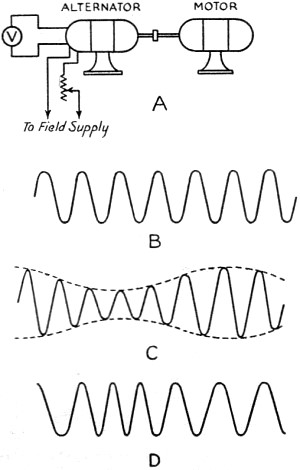
Fig. 1 - Illustrating amplitude and frequency modulation. A, the motor-driven alternator used as an example; B, output with constant field and constant speed (sine wave); C, output with constant speed and variable field (amplitude modulation); D, constant amplitude and variable speed (frequency modulation).
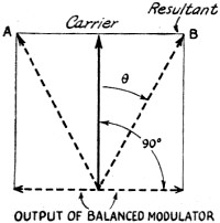
Fig. 2 - Vector Diagram of phase modulation. The modulator vector reverses, producing a resultant Θ degrees ahead or behind the carrier vector. This is equivalent to a sudden change in the time axis, with the result that the frequency changes. The vector will oscillate back and forth between A and B at the modulating frequency. The more rapid the oscillation the faster the change in the time axis, therefore the greater the frequency deviation produced.
Fig. 3 - A practicable frequency-modulator circuit, after Weir. The oscillator is frequency-modulated by the a.f.c. tube (modulator) which causes a frequency deviation in proportion to the amplitude of the audio voltage. A small part of the output signal is fed to the converter tube, which is heterodyned by a stable crystal oscillator to give a beat frequency at 1500 kc. The i.f. output operates the rectifier (discriminator) and by providing the modulator with a d.c. bias which varies when the mean oscillator frequency tends to change (a.f.c. action) maintains the carrier frequency constant. Deviations of approximately 30 to 40 kc. may be obtained in the region of 20 Mc. using a 6L6 modulator and 6F6 oscillator. The stability of the system will be determined by the discriminator circuit stability.
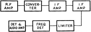
Fig. 4 - Essentials of a superheat receiver suitable for frequency-modulated signals.
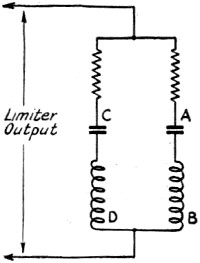
Fig 5. - Elementary detector circuit for frequency-modulated waves. CD is tuned to the lower extremity of useful side bands, AB to the upper extremity. The voltage appearing across either circuit is determined by the amplitude of the audio modulating voltage. A hybrid wave appears across each circuit. Rectification recovers the audio component.
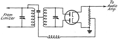
Fig. 6 - The discriminator circuit combines the functions of frequency detector and rectifier to recover the audio signal.
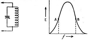
Fig. 7 - A parallel-resonant circuit will act as a frequency detector when tuned to carrier at points A or B. With the circuit tuned so that the carrier is at A. The voltage across the circuit will rise and fall in step with the deviation produced by the modulating voltage; the result is an amplitude- modulated wave which is also frequency-modulated. A rectifier will recover the amplitude audio component.
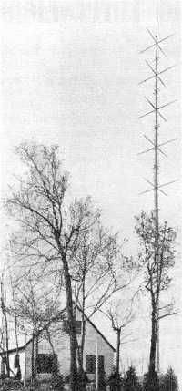
Transmitter house and six-bay turnstile antenna at W1XPW, a 1000-watt experimental frequency-modulated transmitter located on top of West Peak, Meriden Mountain, near Meriden, Conn. The transmitter operates on 43.4 megacycles. WDRC, Inc., is the owner. Two 50,000-watt experimental transmitters and several lower-powered transmitters will be placed in regular operation in the Fall using the Armstrong frequency-modulation system. The marked noise suppression which is the important characteristic of the system will make possible a new standard of high-fidelity reception. The writer has been asked to explain the action of this frequency-modulation system without too much technical terminology. With all qualifications aside, the picture looks something like this: Every amateur knows what frequency modulation is - it's something in his transmitter operation that he doesn't want! To make the picture a little more exact, we shall make use of a pure sine wave alternator. A pure sine wave is a single-frequency wave; that is, no side bands and no harmonics will be associated with it. A perfect frequency meter could locate only one frequency with such a wave. If our alternator is the usual motor-driven type with an external field supply, we can vary the voltage output of the alternator by varying the field current. Let's vary the field current slowly up and down and observe the result. First, the output voltage of the alternator will increase and decrease, and we have a condition commonly referred to as amplitude modulation. See Fig. 1 (A, B, and C). Second, the output wave is no longer a pure sine wave, and if we examine the wave with our perfect frequency meter we shall find several frequencies present, because only the pure sine wave will be limited to a single frequency. So much for amplitude modulation. Frequency Modulation Now regulate the field supply so that the amplitude of the alternator output will not change while the driving motor is made to speed up and slow down. The frequency of the alternator will be determined by the speed of the motor; if we speed up the motor the output frequency will increase, and it will decrease when the motor slows down. Assuming that the amplitude of the output remains constant, we have produced a frequency-modulated wave by the simple process of speeding up and slowing down the motor. What has happened to the wave? First, obviously the wave is no longer a pure sine wave, since the frequency is changing. Second, since the wave is not a pure sine wave, several frequencies will be present (theoretically, an infinite number). When we neglect inertia and speed up and slow down the motor in such a way that the change in speed is at the rate of ten cycles per second, and the cycles are perfect sine-wave cycles, we will produce a frequency series for a 1000-cycle generator something like this: . . . 1000 - 30, 1000 - 20, 1000 - 10, 1000, 1000 + 10, 1000 + 20, 1000 + 30 . . . and so on to an infinite number of side bands. Although frequency modulation will produce a composite wave made up of the carrier, plus and minus a regular harmonic series of the modulating-signal frequency and the carrier, we are fortunate in the fact that the amplitudes of the side bands decrease rapidly as the signal harmonic number increases. To go back to our motor-generator again, the motor was speeded up and slowed down to produce our frequency modulation but we didn't say how much we speeded it up or how much we slowed it down. We can change the motor speed so that the frequency will vary instantaneously as follows: 1000 --> 1025 --> 1000 --> 975 --> 1000 cycles, and make the entire excursion in one-tenth of a second for a modulating frequency of ten cycles per second. Or we can go 1000 -->1050 --> 1000 --> 950 --> 1000 in one-tenth of a second for a 10-cycle modulation frequency. The difference is found in the more extended change in frequency in the second case. This change is called the "deviation." For the first case the deviation is 25 cycles and for the second, 50 cycles. Deviation is then the maximum instantaneous change in frequency. Just to increase the confusion, we might add that we can't find the deviation with the frequency meter since no continuous spectrum is produced but, rather, we produce discrete side bands which may be detected and their physical existence made evident by means of our frequency meter. These side bands may be found far beyond the limits of the deviation. We might define the maximum instantaneous frequency for our special case as the frequency we would get from our alternator if we held the speed constant when the maximum speed was reached. We do not actually produce such a maximum frequency because the speed does not remain constant. All this leads to conclusion that we can expect the band-width of the frequency modulated wave to be greater than twice the deviation. Producing Frequency Modulation A frequency-modulated wave may be produced much more readily with vacuum tube equipment than with rotating machinery. Rotating a condenser back and forth to change the capacity in an oscillator circuit will produce a frequency-modulated wave. Placing a condenser microphone in an oscillator circuit in such a way that changes in the microphone capacity will influence the frequency of the oscillator is an obvious means of producing a modulated wave. The circuit used in automatic frequency control systems is an excellent frequency-modulation system. The modulation method invented by Major Edwin Armstrong is very stable since the carrier is controlled by a quartz crystal oscillator. A 200-kc. oscillator supplies voltage to a phase-shift network from which two components of the carrier are extracted, differing only in phase. One component is 90° out of phase with the other. Mathematically, the difference between the amplitude-modulated wave and the frequency-modulated wave is the difference in the phase relations between side bands and carrier. If the side bands of an amplitude-modulated wave could be extracted from the carrier, shifted in phase 90°, and then recombined with the carrier, a frequency- modulated wave would result. Major Armstrong did not extract the side bands but he did arrange to produce side bands without a carrier by means of a balanced modulator working with one of the 200-kc. components mentioned above, and then to combine the side bands with the second component in such a way that the side bands were 90° out of phase with the normal arrangement for carrier and side bands in the amplitude modulated wave. His result was a frequency-modulated wave of the special type sometimes referred to as a "phase-modulated" wave. Another way to describe the action of Major Armstrong's modulator is to say that he combined a carrier voltage with a side-band voltage which had been rotated through 90°. This gives us the simple picture of two vectors 90° out of phase combining to give the resultant voltage. Fig. 2 will assist the reader to visualize the process. As the side-band voltage is increased and decreased, the resultant of the two vectors is caused to shift phase. The shift in phase corresponds to a frequency change, and the amount of frequency change produced will depend upon the magnitude of the phase shift and upon how rapidly the phase shift is taking place. Since the magnitude and the speed of the phase shift is determined by the side-band vector, the deviation produced will be determined by the magnitude and the frequency of the modulating signal. The only difference between pure frequency modulation1 and phase modulation is the fact that the deviation is a function of the amplitude only of the modulating signal for pure frequency modulation while the frequency of the signal also determines the deviation for phase modulation. A network placed in the audio input amplifier making the output signal voltage inversely proportional to frequency will make the overall response independent of signal frequency, and thus the phase modulator will produce a pure frequency-modulated wave. The actual deviation produced at 200 kc. is small, something of the order of 15 to 20 cycles. Therefore, a series of doublers must be introduced to increase the maximum deviation to 100 kc. A total of twelve or thirteen doubler stages is used to reach the required deviation. A system of modulation suggested by Murray C. Crosby and developed by Irving R. Weir makes use of the automatic frequency control variable oscillator for modulating the frequency, and of the a.f.c. discriminator circuit for stabilizing the oscillator carrier. Fig. 3 illustrates the type of circuit used. The modulator tube injects 90° out-of-phase current into the oscillator tank circuit. The effect of changing the modulator injector current is comparable to changing the tank capacity in the oscillator circuit. The stabilizing circuit functions in the usual a.f.c. manner. Receivers The receiver requirements are not so complicated as one might suspect. The usual super-heterodyne is used with a few additions and changes. The pass band must be greater than twice the transmitter deviation. A limiter precedes the detector, and this limiter has the very important function of "wiping off" any amplitude modulation which may have been introduced by noise voltages. The limiter passes on the frequency-modulated wave with constant amplitude to the frequency detector, which changes the frequency-modulated wave into a hybrid wave with both amplitude and frequency modulation components. An ordinary detector then recovers the signal from the amplitude component. Fig. 4 illustrates the line-up. Figs. 5 and 6 show two frequency detectors. A simple circuit of the type shown in Fig. 7 also will act as a frequency detector. The carrier is tuned in on one side of the resonance curve. A steady-state r.f. voltage will result from the unmodulated carrier, and modulation will produce instantaneous frequency changes. Taking A as the operating point, any change corresponding to an increase in frequency of the signal will increase the amplitude of the voltage across the parallel-resonant circuit, and an equivalent decrease in frequency will decrease the voltage across the circuit. Therefore, since the modulation produces magnitudes of frequency change or deviation corresponding to the amplitude of the audio modulating signal, and since the rate at which the changes or deviations take place corresponds to the frequency of the audio signal, the voltage appearing across the parallel-resonant circuit will be amplitude-modulated. Frequency modulation will also be present but we are no longer interested in that. Rectification will recover the audio signal. Any receiver of the usual type can be made to receive frequency- modulated signals after a fashion by detuning slightly, but the reader is assured that the "fashion" is not very satisfactory. Noise Suppression Remarkable results in the suppression of noise and interference are possible with the frequency modulation system. Since the limiter wipes off all amplitude variations, noise of this type must appear as frequency modulation produced by the phase shift resulting from the combination of the signal and noise voltages. For the case where the peak noise amplitude is half the signal amplitude and the phase relation between signal and noise is ninety degrees, the maximum phase shift would be approximately 26.5°. Very little frequency modulation will be produced if this phase shift is the result of noise modulated by a low-frequency audio component, but the frequency modulation will increase directly with the frequency of the audio noise component. The receiver will display greatest susceptibility to noise frequencies above audibility. Logical design of the receiver would call for a sharp cut-off of the audio amplifier response or, better still, a falling high-frequency characteristic which will reduce the hiss response. A simple predistortion network at the transmitter will present a compensating rising high-frequency response so that the overall response of the system is flat. This is the arrangement used in the stations now on the air. The very remarkable effect of the limiter action upon the suppression of interference has been demonstrated by Weir.2 He reports that with two stations operating on the same channel the stronger station would prevail 100 per cent at the receiver whenever the stronger station's signal was more than twice the strength of the weaker signal. He also reports in the same paper that no interference area of the usual kind existed where the signals were of nearly the same amplitude. In this area the movement of the antenna a few inches would throw one program out and bring in the other one. The presence of standing waves accounts for the phenomenon since the nodes would permit the selection of the required voltage radio. Mathematically the action of the limiter is rather complicated, but the results of the limiter action are an overall effect of cutting the amplitude of the received voltage in such a way that the strong signal component dominates while the weak signal is suppressed. In other words, the strong signal will always take control of the receiver. The frequency-modulation system permits2 as much as 25 dB gain in signal-plus-noise- to-noise ratio over that possible with an amplitude system of equal carrier strength. While this gain in equivalent power is due in part to the limiter action it is also the result of the very interesting effect which makes the magnitude of the recovered power at the receiver a function of the modulation deviation. If a deviation of 50 kc. produces voltage A at the receiver, then a deviation of 100 kc. will produce a voltage two times A at the receiver. Here the received voltage has been doubled without changing the carrier power at the transmitter. In the amplitude case the peak carrier power must increase four times when the modulation changes from zero to 100 per cent. Since without the power change the received voltage increases for the frequency-modulated system with an increase in deviation, it follows that the advantage of the system over the amplitude system will increase as the deviation is increased. The practicable limits must be determined by available channel width. The Federal Communications Commission has assigned 200-kc. channels for the broadcast stations now in operation. For this channel width the deviation will probably be restricted to 80 kc. or less. Present standards seem to point to a modulation index (that is: ratio of deviation to audio frequency) of 80,000/15,000' or approximately 5.3. Necessarily this is a very sketchy account of Major Armstrong's invention. The writer hopes that it may serve as an introduction to the subject, and for those who are interested in the more detailed and technical aspects a carefully selected bibliography is appended.
Selected Frequency Modulation Bibliography 1. Carson, John R. "Notes on the Theory of Modulation," Proceedings IRE, Vol. 10, No.1, February, 1922. First paper in which the frequency-modulated wave is analyzed mathematically and the required "band width" determined. 2. Armstrong, Edwin H. "A Method of Reducing Disturbances in Radio Signaling by a System of Frequency Modulation." Proc. I.R.E., Vol. 24, No.5, May, 1936. Undoubtedly the classical paper in the field. The first published account of the wide-band frequency modulation system. 3. Crosby, Murray C. "Frequency Modulation Noise Characteristics." Proc. I.R.E., Vol. 25, No.4, April, 1937. Mathematical treatment and experimental verification of wide-band frequency modulation vs. amplitude noise suppression. 4. Roder, Hans. "Frequency Modulation." Electronics, Vol. 10, No.5, May, 1937. Mathematical analysis of validity of noise-suppression effect in wide-band frequency modulation. 5. Carson, John R. and Fry, Thornton C. "Variable Frequency Electric Circuit Theory with Application to the Theory of Frequency Modulation." Bell System Technical Journal, Vol. 16, No.4. Fundamental formulas for variable frequency electric circuit theory are developed. Transmission, reception and detection of frequency modulated waves are studied analytically. 6. Roder, Hans. "Tuned Circuits and a Frequency Modulated Signal." Proc. I.R.E., Vol. 25, No. 12, Mathematical treatment of tuned circuits. 7. Weir, I. R. "Field Tests of Frequency-and-Amplitude-Modulation with Ultra-High-Frequency Waves." General Electric Review, May, 1939, Part I; June, 1939, Part II. A very important paper of interest to both the technical and non-technical readers. Describes a simplified transmitter. 8. Day, John R . "A Receiver for Frequency Modulation." Electronics, June, 1939. The first published constructional data for a seven-tube frequency-modulation receiver.
Posted May 29, 2020 |
||