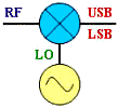
foutput
= ±finput ±fLO
This description of the phenomenon of spectral inversion was written for the
RF Cascade Workbook 2005 user's manual, and provides a unique
pictorial representation of what is happening when a frequency mixer multiplies
two frequencies together.
See
Espresso Engineering Workbook (free) for a calculator.
All four combinations of the mixing equation shown next to the mixer above are
covered. Figures A and B, below, are equivalent results for both the LO-RF and the
RF-LO cases. In case A, the subtraction results in negative frequencies, but the
negative terms are said to be “reflected” or “folded” about the 0 Hz (DC) axis.
The subtraction in case B does not produce any negative results, so there is no
need to mathematically reflect it about the 0 Hz axis. There is no real physical
reflection mechanism occurring, it is merely a mathematical convenience. The mixer
has no way of determining which frequency is being subtracted from the other, regardless
of how you happen to write the equation.
No spectral inversion occurs in either the upper sideband (USB) or the lower
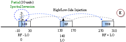
sideband (LSB) with a low-side LO injection (cases A and B). However, with a high-side
LO injection, the LSB will exhibit spectral inversion while the USB does not (cases
C, D and E). An explanation of spectral inversion is provided in the next paragraph.
First, though, note that with a high-side LO there is an equivalent subtraction/reflection
pair similar to the low-side LO case. Case E is a special case where the LO functions
as both a low-side and a high-side signal. There, a portion of the band experiences
spectral inversion while the other portion does not (termed "frequency folding").
Spectral inversion occurs when the lower sideband of a high-side injected LO
is used for the output, like examples C, D and E. The result is the lower frequencies
of the input band being translated into the upper frequencies of the output band,
and vice versa. Shading and arrow-tipped lines are used to track the relative band
edges. A second inversion will cancel out the original, but a third will reintroduce
the inversion, and so on. Digital systems can un-invert the spectral inversion in
software or firmware if it knows to expect it. However, spectral inversion of analog
voice information results in unintelligible garble. If multiple conversions are
required, then an even number of inversions will result in no net inversion at the
output while an odd number of inversions will always result in a net inversion at
the output.
Posted October 6, 2004
|


