Carl & Jerry: TV Antennas
|
|||||||
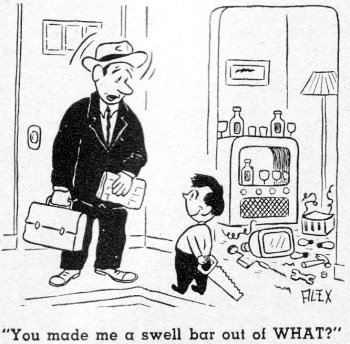
In this episode of Carl & Jerry, the teens ponder a question posed by Jerry's mother upon looking down their hillside home: "[L]ook at all those TV antennas down there. Hardly two of them are alike; yet they're all intended to receive the same stations. How come there are so many different kinds?" That was all the pair needed to set them off in an investigation to determine the answer. Being avid electronics and RF hobbyists and experimenters, they discuss the principles of how antennas work, various types of transmission lines, impedance matching, antenna types, bandwidth, and other topics relevant to the challenge. As with most Carl & Jerry stories, the intent is to educate the reader. As a bonus, I posted two of the electronics-related comic panels that were in this edition of Popular Electronics. Carl & Jerry: TV Antennas
The two boys climb a hill, then talk about kinds of TV antennas and how they work The hot August sun beat down on the two boys climbing up the steep path. Lanky, athletic Carl Anderson scarcely breathed hard as he forged steadily up the hill; but behind him his overly plump chum, Jerry Bishop, puffed like a steam locomotive as he toiled along the steep ascent. In spite of his noisy effort, Jerry kept falling farther and farther behind, and finally he came to a full stop and collapsed in the shade of a huge boulder beside the path. "How come you're dropping anchor there, Blimp Boy?" Carl called down. "We've still got a quarter of a mile to go to the top." "I can never make it," Jerry gasped feebly. "Go on without me. Just say my spirit was willing but the flesh was weak. Leave me a dozen sandwiches or so to make my last moments comfortable."
"You wouldn't dare!" Jerry cried, with the quick instinctive anger of a hungry dog who sees his bone suddenly snatched from him. "Oh no?" Carl said tauntingly, as he squatted on his heels and opened the lunch basket he was carrying. Very deliberately, he removed a thick paper-wrapped sandwich . and slowly pulled out the toothpick thrust through it. With a snarl of mixed hunger and rage, Jerry leaped to his feet and charged up the path toward his tormenter. Carl barely had time to toss the sandwich back into the hamper and scramble upward out of Jerry's clawing reach. The latter was so incensed by the horrifying prospect of Carl's eating all the lunch that he did not slacken his pace and the two boys arrived at the top almost neck and neck. "You made it!" Carl congratulated, as he flung himself at full length on the thick grass beneath a tree. For a minute, Jerry stood over him with his face still wearing its menacing scowl, but then as he looked about and realized he had actually reached the summit, his round countenance broke into a pleased grin and he sat down abruptly beside his friend. "We better cool off a little before we eat," Carl suggested. "It certainly is a wonderful view, isn't it?" "It sure is," Jerry agreed, with his head buried in the picnic hamper. "Now that we've cooled off for at least a couple of hundred seconds. let's eat. Do you want your tenderloin sandwich with or without .mustard?" There was little conversation for the next few minutes as the boys waded through the assorted sandwiches, hard-boiled eggs, and fresh fruit that Carl's mother had provided. Finally, though, when they were munching their chocolate bar dessert, Carl said lazily: "Jer, look at all those TV antennas down there. Hardly two of them are alike; yet they're all intended to receive the same stations. How come there are so many different kinds?" Jerry pillowed his head on his clasped hands and stared up at the fleecy white clouds drifting across the blue sky overhead. "To answer that properly really takes a lot of doing," he said slowly. "You almost have to go into the subject of how TV antennas work." "So let's go into it," Carl promptly urged. "I've got the time, and you think you've got the information." "When TV broadcasting first started," Jerry began, "the receivers were invariably close to the transmitter, and the engineers simply adapted the old standby short-wave receiving antenna, the half-wave dipole. This is simply a conductor which is an electrical half-wavelength long at the frequency being received and which is cut in two at the middle so that each half feeds into one part of a two-conductor feedline, such as a twisted pair, coaxial cable, or piece of twin-lead. In radio work, the conductor is usually wire; but since a half wave is only a matter of a few feet on the TV frequencies, the TV antenna was made up of a couple of pieces of aluminum tubing secured to a center block of insulation." "I don't see anything like that down there," Carl remarked as he raised himself on an elbow and looked down at the rooftop antennas.
"I don't dig this impedance-matching business as well as I might," Carl admitted. "Every piece of equipment that generates, carries, or receives r.f. currents has a certain amount of built-in opposition to the flow of those currents that is called 'impedance,' " Jerry explained, beginning to enjoy his role of lecturer. "In order to transfer the maximum amount of power or signal from one piece of equipment to another, their respective impedances must be equal or 'matched.' If the TV antenna is not matched to the feedline and if the feedline is not matched to the receiver, you not only lose a lot of signal but the mismatch is likely to generate annoying ghosts in the picture. Most TV sets are built with an antenna input impedance of 300 ohms. Low cost and efficient twin-lead designed to match this also has a 'surge' impedance, as it is called, of 300 ohms. But if you have to feed a 72-ohm half-wave dipole antenna into the end of this 300-ohm feedline, you have a 4 to 1 mismatch." "And I guess a 52-ohm coax line would be worse?" "It can be done, and some receivers have a 52-ohm input for this line, but it is much more expensive than twin-lead and has a much higher loss than a good grade of dry twin-lead. It was easier to change the dipole so that its impedance would match the inexpensive 300-ohm flat line." "How did they cut that caper?" "Just by placing another conductor a half wavelength long three or four inches above the dipole and connecting its ends to the outside ends of the dipole. This changed the simple dipole into a 'folded dipole,' with several important advantages. For one thing, the antenna impedance was quadrupled so that it was almost an exact match for the 300-ohm line. Secondly, the frequency response of the folded dipole is much wider than that of the simple dipole." "Wait up!" Carl commanded. "What's this jive about widening the frequency response?" "The dipole delivered maximum received signal strength only on the channel for which it was cut. Signals on adjacent channels excited much less response in the antenna, and signals from channels still farther removed from the antenna's resonant frequency produced still less response. Since the antenna responded only to signals close to its resonant frequency, we say it had a narrow bandwidth. The folded dipole responds much more strongly to signals on adjacent channels, so we say it has a wider bandwidth. Catch?" "Roger. With a wide-band antenna, you can receive several channels on the same antenna. With a narrow-band job, you can receive only one channel well." "I do believe you're getting brighter!" Jerry said sarcastically. "At any rate, the folded dipole still did not have all the answers. Especially, it did not prevent receiving a station just as well off the back as the front. To correct this fault, TV design engineers borrowed the Yagi antenna radio hams had been using on 10 and 20 meters for years. To change a folded dipole into a Yagi, you mount the dipole horizontally on a long horizontal boom. On this boom, parallel to the dipole, you mount several other metal rods or tubes called 'parasitic elements' because they have no direct connection to the 'driven element' that is connected to the feedline. Parasitic elements on the front part of the boom are called 'directors,' and they are a trifle shorter than the driven element and must be mounted at certain critical distances ahead of that element. At the rear of the boom, also at a critical distance, is mounted a parasitic element called a 'reflector' that is somewhat longer than the driven element.
"Sounds like the perfect answer to the TV antenna problem" "For single-channel reception, it's hard to beat - but there's the rub. In its conventional form, a Yagi is a very narrow-band affair good for reception only of the single channel for which it is designed. Lately, however, the engineers have given the old Yagi a new look by working it over into what is known as the broadband Yagi - capable of yielding good signal strength and excellent on all 12 v.h.f. channels. This is done by using more than one driven element and by carefully adjusting the length and spacing of the parasitic elements so that they do double or triple duty, producing effectively the equivalent of several different Yagi antennas mounted on a single boom. That antenna over there, next to the church, which is called an 'Interceptor,' is a good example of this design." "How about those jobs with the elements sticking out every which way? I think they are called conicals." "Well, going back to our original dipole, increasing the physical size of the dipole elements will widen the frequency response. Theoretically, the best way to do this is to use metal cones mounted tip-to-tip for the elements. The cones can be flattened into triangular sheets of metal without much loss of effectiveness, and this is actually done on the u.h.f. channels. The resulting dipoles are called 'bow-ties' because of their appearance, and are usually mounted in front of a reflecting metal grid or inside the jaws of two such grids edge-connected at a 90° angle to form what is known as a 'corner reflector.' "On the v.h.f. channels, where wavelengths are measured in feet instead of inches, a bow-tie of proper dimensions would be too bulky and expensive and have too much wind resistance. However, metal rods or tubes that preserve the outline of the bow-tie, and that might be considered the skeleton of the original cones, serve almost as well. By inclining the skeleton wings of this 'conical' dipole slightly forward to form a shallow funnel, reception on the higher channels is improved. TV signals are directed in toward the feedline point in much the same way that sound waves are collected by an old-fashioned hearing trumpet. A skeleton bow-tie reflector is usually mounted behind the conical antenna to improve the front-to-back ratio. To get still more strength in fringe areas, it is a common practice to stack two, four, or even more of these conical 'bays,' as they are called, one above the other on the same mast, and connect them to a common feedline. To insure that the signals picked up by the several bays actually reinforce instead of buck each other, it's necessary that bays be mounted the proper distance apart and that they be connected together with special 'stacking harness.' " "Any more TV antennas?" Carl asked drowsily. "Lots more, but you'd never stay awake to hear about them," Jerry observed tartly. "Some antenna manufacturers depend upon stacking several dipole-and-reflector bays vertically for increased gain. Half-wave elements, properly phased, may be mounted side by side and several such bays stacked to form what is called a 'collinear array.' The appearance of such an antenna, together with a reflecting screen, has given rise to its popular nickname of 'the bedspring antenna.' Other manufacturers combine Yagi and conical antennas on a single boom, hoping to get the benefits of both from this marriage."
"That's the ratio between the signal voltage delivered by the antenna to the feedline on a certain channel and the voltage delivered by a reference dipole antenna cut to the frequency of that channel and mounted in the same spot. This ratio is expressed in decibels. For example, if the antenna under test delivers twice as much signal voltage as does the dipole on Channel 6, we say it has a 6-db gain on that channel. If it delivers four times the voltage, it has a 12-db gain." "What characteristics would you say the perfect TV antenna should have?" "First, it should have high gain; second, it should maintain this gain across all v.h.f. and u.h.f. channels with no peaks or dips; third, it should present a consistent 300-ohm impedance to the feedline on all frequencies; fourth, it should have a single, narrow reception lobe and should present infinite rejection to signals arriving from the side or rear; and finally, it should be cheap, light, and easily mounted, with a low wind resistance and a beautiful appearance." "Sounds like quite an order." "It is, especially when you realize that antenna gain, bandwidth, front-to-back ratio, and impedance are all closely interlocked so that you cannot vary one of them without changing all the others. And right there you have your answer as to why there are so many different kinds of antennas. Each manufacturer tries a different compromise in his approach to this ideal antenna. One may stress high maximum gain or front-to back ratio; another advertises price and appearance; still another may boast that the response curve of his antenna has no sharp dips and valleys in it - something especially important in an antenna used for color TV reception. Each advertising claim appeals to a certain group of customers who feel that the stressed characteristic is just what they need to solve their reception troubles. If it doesn't, then they are ready to try another new antenna, always hoping they will eventually come across the perfect TV antenna which will insure perfect reception all the time." "You sound a little cynical about this." "I'm not really. I know how important it is to have a good antenna, especially in a weak-signal area; but I also know for a fact that the TV antenna can only do so much. It cannot receive a signal that just isn't there; nor can it compensate, beyond a certain point, for a poor receiver. The TV antenna is like the automatic choke on a car; it gets a lot of blame for 'sins' of which it is not guilty." Carl rose and brushed the grass from the seat of his pants. "Well, I guess we had better be starting for home, Marconi. Do you think you will be able to totter down the hill or had I better just roll you like a barrel?" "Don't get smart with me," Jerry said, as he struggled to his feet, trying not to wince at the protest from his sore muscles, "Just don't get in my way going down as you did coming up."
Posted December 6, 2019 |
|||||||
 By John T. Frye
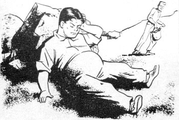

 Carl & Jerry, by John T. Frye