|
August 1960 Electronics World
 Table of Contents
Wax nostalgic about and learn from the history of early electronics. See articles
from
Electronics World, published May 1959
- December 1971. All copyrights hereby acknowledged.
|
The first installment of
this two-part "Computer Memory Devices" series discussed the use of magnetic data
storage in the form of drums and tapes. Both types provide long-term, non-volatile
storage, but both suffer from a relatively slow execution of writing and reading
to and from, respectively, the media. In 1960 when Electronics World magazine
printed the articles, drums and tape were used during execution of programs because
electronic storage in the form of vacuum tube circuits was extremely costly in terms
of power, cost, and physical space. As recently as the early 1980's, magnetic
tape storage still dominated the data storage field, especially where huge amounts
on information needed to be stored and retrieved. Semiconductor memory, while less
voluminous and less power hungry, still added a lot to the cost of computers. If
you were around at the time and used a PC, you remember that 64 kilobytes or RAM
was considered high end and many (maybe most) off-the-shelf PCs came with just 16
kB or 32 kB of RAM. As reported in Part 2, the advent of
magnetic core memories greatly improved the speed of I/O operations, but it
was also expensive because building the arrays was very labor intensive, requiring
assemblers to thread hair-thin wires through the tiny cores.
Computer Memory Devices - Part 2

Fig. 11 - Direction of core magnetization determines whether
binary 1 or 0 is stored.
By Ed Bukstein, Northwestern TV & Electronics Inst.
Not limited by mechanical delays, magnetic cores provide speedier access time
than tape or drums.
Of the various means for magnetically recording and storing data in the "memory"
sections of electronic computers, two were described in the first portion of this
article. These two, magnetic tape and magnetic drums, were found to complement each
other. While the former provides the greater storage capacity, the latter permits
quicker access to any desired portion of the information being held for use.
Because of these characteristics, many computers use these two in combination,
with the drum serving as the main memory and the tape providing back-up storage.
Blocks of information are transferred from the tape to the drum at some time prior
to the need for that data in the computer. After the computer has made use of this
data, other blocks of information can be transferred to the drum. However, there
are some applications where it is desirable to have even shorter access time than
that provided by drums. In these, magnetic cores are used for the main memory. In
fact, the drum may then become the back-up storage device.
The magnetic core is a ring-shaped piece of magnetic material. Since the core
can be magnetized in either of two directions (clockwise or counterclockwise), it
can be used to store a bit of binary information. Magnetization of the core in one
direction can be used as a representation of binary 1, and magnetization in the
opposite direction can represent binary 0. The binary number 10101, for example,
can be stored in five magnetic cores as shown in Fig. 11. Here the arrows indicate
direction of magnetization.
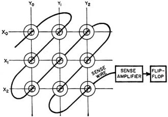
Fig. 12 - Perpendicular wires magnetize cores, sense wire picks
up the data.
Physically, the magnetic cores are small - 0.08 inch outside diameter is representative-and
are placed on an array of perpendicular sets of wires, as shown in Fig. 12. For
simplicity, a 3-by-3 array of cores is shown here, but 32-by-32 and 64-by-64 arrays
are commonly used in practice.
Information is written into a core by passing currents through the wires on which
the core is mounted. Assume, for example, that all of the cores in Fig. 12 are initially
magnetized in the 0 direction, and that it is desired to store a 1 in the core located
at the intersection of wires X1 and Y2. This would be accomplished
by passing currents through wires X1 and Y2 simultaneously.
The values chosen for these two currents are such that either one individually is
not sufficient to reverse the magnetization of the core, but the combined effect
of both at the intersection X1Y2 is sufficient to reverse
the core at this location.
The individual currents are frequently referred to as half-currents because each
has a value equal to half of the total current required to reverse the magnetization
of the core. This technique, known as coincident-current switching, makes it possible
to write a 1 in any selected core by passing half-currents through the appropriate
X and Y wires.
The process of reading a core is somewhat similar to the writing process, except
that the currents are passed through the X and Y wires in a direction opposite that
used for writing. Assume, for example, that the core at X1Y2
is to be read. This would be accomplished by passing half-value "read" currents
through wires X1 and Y2 simultaneously. These read currents
are al-ways in such direction as to switch the selected core to the 0 direction
of magnetization. The read currents will therefore switch core X1Y2
to the 0 direction, and the reversing magnetic field will induce voltage in the
sense wire. This output, which is a few millivolts in amplitude, is amplified (by
the sense amplifier in Fig. 12) and then used to trigger a flip-flop stage. As a
result, the flip-flop stage is now switched to the 1 condition, and the 1 which
was previously stored in core X1Y2 has now been transferred
to the flip-flop.
If core X1Y2 had been in the 0 rather than the 1 condition,
the read currents would not have reversed this core's magnetization. Under these
conditions, there would have been no output from the sense wire and the flip-flop
would have remained in the 0 condition. The read currents therefore cause the flip-flop,
in either case, to assume the condition (0 or 1) of the core being read.
Since reading a core which has a 1 stored in it causes this core to switch to
the 0 condition, the read-out process destroys the information in the core (although
the information is still available in the flip-flop). For this reason, the reading
operation is followed by a writing operation to switch the core back to the 1 condition,
so that it may retain stored data.
In addition to the wires shown in Fig. 12, one other wire, not shown, is threaded
through all of the cores in the array. This is known as an inhibit wire and is used
during the process of writing. As explained previously, a 1 can be written into
a selected core by passing currents through the associated X and Y wires. If however,
a 0 is to be written into the core, something must be done to prevent the write
currents from switching this core to 1. This is accomplished by passing a half-current
through the inhibit wire at the same time the two half-currents are passed through
the X and Y wires. The inhibit current is in such direction that it opposes the
write currents and therefore prevents the selected core from being switched to 1.
At first consideration, it may seem more reasonable to write a 0 into a core simply
by preventing the write currents from passing through the X and Y wires. It happens
that the associated circuitry, however, is much simpler if the write currents are
used but nullified by an inhibit current.
Since the cores in an array are selected for reading or writing on a one-at-a-time
basis, this type of storage would be relatively slow if all of the bits of a given
number were stored in the same array. Under these conditions, a number would have
to be written (or read) one bit at a time. For this reason, each bit of a number
is stored in a separate array of cores. Each of these arrays is known as a plane.
Each of the cores shown in Fig. 11 would therefore be placed at corresponding locations
in five different planes and could be read or written simultaneously. The total
storage capacity of a core memory is determined by (1) the number of cores in each
plane and (2) the number of planes. A twelve-plane 64-by-64 memory would, for example,
be capable of storing 4096 twelve-bit numbers.
Magnetic drum and tapes are cyclic storage devices, involving mechanical motion
of the recording surface with respect to the heads. Recorded data passes the reading
heads in the order in which the data is located on the surface of the drum or tape.
By contrast, magnetic cores constitute a random-access type of storage. This means
that the cores can be read in any order at once simply by pulsing the appropriate
X and Y wires. It is for this reason that the access time is very short as compared
to tape or drum storage, and magnetic cores are frequently used in the main memory
of high-speed computers.
Posted January 2, 2023
|