Computer Memory Devices - Part 1
|
|
In 1960 when this "Computer Memory Devices" article appeared in Electronics World magazine, digital electronic computers were still a relatively new technology. Although bulky and power-hungry, accomplishing digital manipulations of data for logic, mathematics, sorting, etc., was relatively easy, but unless programming instructions were fixed and output was used real-time, an ability to store data is necessary. Memory banks composed of vacuum tubes could - and often did - do the job, but the data was neither permanent nor physically transportable. If power is lost, the information is lost. We still suffer that issue even today volatile type memory. For more permanent data storage, magnetic media was developed, solving both aforementioned down sides of electronics memory. This two-part article by Mr. Ed Bukstein, of the Northwestern TV & Electronics Institute, delves into the state of the art back in the day. Computer Memory Devices - Part 2 was in the August 1960 issue of Electronics World. Computer Memory Devices - Part 1
For speed and automation, storing information is important. Magnetic tapes and drums are used. By Ed Bukstein Northwestern TV & Electronics Inst. As compared to mechanical calculators such as the ordinary adding machine, the electronic computer has two important advantages: high speed and automatic operation. Both of these advantages result from the use of memory or storage devices. The numbers to be used in calculation and the instructions which specify the types of operations to be performed (addition, subtraction, etc.) are stored in the memory device before the calculation begins. The computer then extracts this information as it is needed during the course of the computation. As a result, the computer is able to perform a lengthy series of calculations without the intervention of a human operator. In this sense, the computer is automatic. By contrast, the operator of an office-type adding machine must punch - in new information (through the key- board) before each individual step of the calculation. Since the machine is "idle" during the time the operator is entering new information into the keyboard, the calculation progresses at a relatively slow rate. A full day's work might therefore be required to complete a calculation which an electronic computer could perform in a matter of seconds. The memory section of a computer is also used to store partial answers, obtained in early steps of a calculation, which may be required in a later step. Final answers are also stored in the memory and, at some convenient time, can be transferred to a print-out device, such as an electric typewriter. Many computers are so designed that the print -out function can be performed while the computer is simultaneously working on another problem.
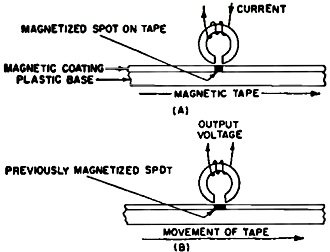
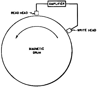
Fig. 1 - As with sound, electromagnetic heads (A) record and (B) play back data.
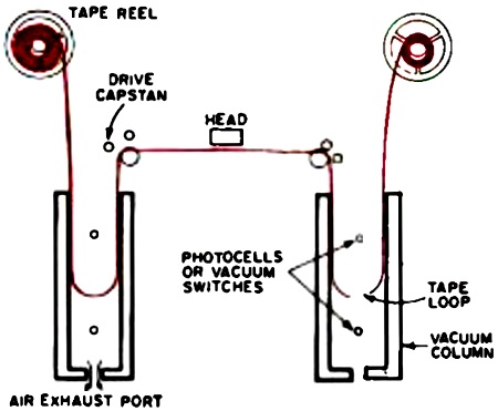
Fig. 2 - Tape-tensioning vacuum columns permit rapid, harmless stops and starts.
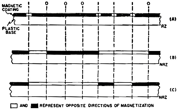
Fig. 3 - In return-to-zero (A) recording, binary 1 is represented by tape magnetization in one direction and binary 0 by magnetization in the opposite direction. In non-return-to-zero recording, direction of magnetization is changed (B) only when switching from one digit to the other or (C) only when 1 is recorded.
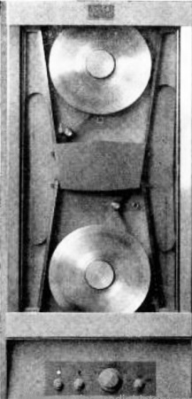
Fig. 4 - Upper portion of rack-mounted Ampex FR-300 digital tape handler with standard speed of 150 inches per second and a fast speed of 225 ips.
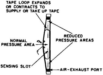
Fig. 5 - Detail of one of the vertical vacuum columns used in the handler of Fig. 4. Compare this arrangement with the one highlighted in Fig. 2.
Fig. 6 - Access time of a magnetic drum is shorter than that for a reel of tape
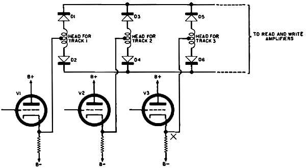
Fig. 7 - Although heads for magnetic drums are in parallel, they are isolated from each other by one-way semiconductor networks.
Fig. 8 - The magnetic drum of this Royal McBee LGP computer, which can be seen passing under the heads, stores 4096 words.
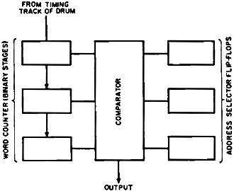
Fig. 9 - To select specific stored data, comparator produces output only when right number is fed from timing track.
Fig. 10 - A quick-access loop makes data available in less than one revolution by constantly repeating this data. Magnetic Tape Storage The magnetic tape recorders used for data storage in digital computers differ in physical detail, but not in basic principle, from those used for audio recording. This basic principle is illustrated in Fig. 1. As shown, the tape consists of a plastic base coated with a thin layer of magnetic oxide. This tape is moved through the machine by a motor-driven transport mechanism. The path of the tape is such that the magnetic coating passes adjacent to the air gap in the write head (Fig. 1A). If a pulse of current is passed through the coil of the write head, magnetic lines of force will be established in the core. These lines of force bridge the air gap by flowing through the magnetic coating of the tape. The section of tape under the air gap therefore becomes magnetized as a consequence of the current flow through the write coil. Playback, known as reading in computer terminology, is accomplished by moving the tape adjacent to the air gap of a read head (Fig. 1B). As the magnetized tape passes the gap, a magnetic field is established in the core and the lines of force cut across the coil. The voltage induced in the coil constitutes the output. In computer practice, the same head is used for both writing and reading. This is permissible because the two operations do not occur simultaneously. Information is recorded in a number of parallel tracks across the width of the tape and a separate head is provided for each track. Binary -coded decimal, excess -3 code, and 7 -bit code are frequently used for storing data on magnetized tape (see "Numbers Systems and Codes," Electronics World, November 1959) . Recording is interrupted at periodic intervals so that the information is recorded in blocks. Typically, each block of information occupies about an inch of tape length, and the blocks are separated by about a quarter inch of blank tape. Such grouping of the recorded material is an aid in locating and selecting desired data for read -out. Counting circuits that respond to the passing blocks of information activate the reading circuits when the desired block passes under the reading heads. In audio recording, the degree of magnetization of the tape is an important factor and varies with the audio signal being recorded. In computer applications, however, the direction of magnetization is the important factor and the degree of magnetization con- veys no intelligence. For improved signal -to -noise ratio, the write currents are made sufficient in amplitude to magnetize the tape completely to saturation. The recorded tape is therefore fully magnetized in one direction or the other. Since data is recorded in binary form, one direction of magnetization represents binary 1 and the opposite direction of magnetization represents binary O. This technique, known as RZ (return -to -zero) recording, is illustrated in Fig. 3A. In the method known as NRZ (non -return -to -zero) recording (Fig. 3B), the direction of magnetization of the tape changes only when the data changes from 0 to 1, or from 1 to O. In another variation of NRZ recording, the direction of magnetization changes only when a 1 is to be re corded. As shown in Fig. 3C, each change in the direction of magnetization represents a 1, and the 0 is recorded by maintaining the magnetization in the same direction it had during the previous bit. As compared to RZ recording, the NRZ techniques are characterized by less frequent changes in the direction of magnetization. This is an important advantage because it permits more bits of information to be recorded on a given length of tape. The mechanical requirements of a tape machine designed for computer work are somewhat more demanding than those of a machine designed for audio applications. This is so because the computer tape must be frequently started, stopped, and reversed in direction. To prevent tape breakage and to permit rapid acceleration and deceleration, the tape is allowed to hang in a loose loop on each side of the head, as shown in Fig. 2. The loops hang down into vacuum columns, so that the atmospheric pressure on top of the tape maintains a slight tension on the loops. This arrangement permits the tape to be started and brought up to speed in a very short time because the motor need accelerate only the tape in the loop. The other reel and the remaining tape "catch up" a short time later. Start and stop times of five milliseconds are typical. Each reel has its own motor, and a servomechanism con- trol prevents the loops from becoming too short or too long. The servomechanism responds to signals supplied by either pressure switches or photocells located in the vacuum columns. The Ampex FR -300 digital tape handler, shown in Fig. 4, has a standard speed of 150 inches per second forward or reverse, and a fast speed of 225 inches per second. Start and stop times are 1.5 milliseconds. The tape- tensioning air columns of this machine are constructed as shown in Fig. 5. Air drawn from the exhaust ports maintains tension on the loops, and the loops contract or expand as the tape accelerates or decelerates. To minimize wear, the FR -300 drives on the tape backing rather than on the oxide side. This machine handles either half - inch or one -inch tape widths, providing 8 or 16 recording tracks. Magnetic tape, as a storage medium, offers the advantage of very great ca- pacity. At a packing density of 200 bits per inch, a half -inch tape 1200 feet in length can store literally millions of bits of information. Tape lengths of 2400 and 3600 feet are also commonly used and provide even greater storage capacities. Furthermore, a single com- puter may have at its command a large number of tape machines. One disadvantage of tape storage. however, is its relatively long access time. Since the information required at some particular instant may be out at the far end of the tape, several minutes may be required to bring it under the reading heads. For this reason, computers utilize magnetic tape for reserve storage, but use a medium having a shorter access time for the main memory. The magnetic drum is often used for this purpose. The Magnetic Drum The magnetic drum consists of a motor -driven, aluminum cylinder coated with a thin layer of magnetic oxide. Writing and reading are accom- plished in a manner similar to that used with magnetic tape. In a sense, the drum surface is like a short, wide tape with the ends joined to form a continuous loop. As shown in Fig. 6, many parallel tracks can be recorded on the drum. A twelve -inch drum, for example, may hold 200 tracks of information. The number of bits that can be stored in each track is, of course, determined by the diameter of the drum. Drum diameters from five to ten inches are common, but smaller and larger sizes are sometimes used. Magnetic drums are normally pro- vided with separate heads for each track. It is possible, of course, to use fewer heads so mounted that they can be moved from one track to another. This arrangement however, results in an increase of mechanical complexity as well as an increase of access time. The heads of a magnetic drum may be connected in parallel (through diodes) as shown in Fig. 7. Since the diodes are biased in the non -conducting direction, the heads are effectively isolated from each other. Any given track can then be selected for writing or reading by making the associated diodes conductive. If, for example, a positive control signal is applied to the grid of V, in Fig. 7, this tube will become con- ductive and the voltage at point X will rise from a negative to a positive value. Since diodes DA and D, are now forward biased, the head for track 3 is con- nected to the read and write amplifiers. Drum storage is cyclic, because each revolution of the drum brings the same information under the reading heads. The access time of the drum is therefore determined by the rate of revolution. Since it may happen that the desired information has just passed the reading heads at the time it is needed, the maximum access time is the time required for the drum to complete one revolution. It may happen, however, that the desired information is just ap- proaching the reading position at the time this information is required. In such a case, the actual access time will be much shorter than the maximum access time. For this reason, access time is often specified as an average value, equal to the time required for the drum to make one half revolution. A common value of drum speed is 3600 rpm, but rates in excess of 12,000 rpm have been used. At 3600 rpm, the maximum access time would be 16.7 milliseconds and the average access time would be approximately 8.3 milliseconds. The magnetic drum used in Royal McBee Corporation's LGP -30 computer is shown in Fig. 8. Data on this drum is divided into groups known as words, each of which contains 32 bits including the sign bit (plus or minus) and the spacer bit. The drum holds 4096 such words. The drum surface can be seen in Fig. 8 between the rows of heads. Many computers are designed to handle numbers that are 10 to 12 digits in length. Since each of these decimal digits can be represented in coded decimal notation by four binary bits, 40 to 48 bits are required to represent each decimal number. In addition, another four -bit combination is used to indicate whether the number is positive or negative, bringing the total to 44 to 52 bits. This amount of information is known as a word, and many such words may be recorded in each track of a magnetic drum. To read a particular word from one of the drum tracks, it is necessary to activate the reading circuits just before the first bit of the desired word reaches the head, and to de- activate 8+ the circuits as soon as the last bit of the desired word has been read. For this purpose, a timing track is recorded on the drum as shown in Fig. 6. On this track, a series of pulses is recorded in positions such that each pulse passes under the reading head at a time when the first bit of a word is approaching the reading heads on the other tracks. The pulses from the timing track are fed into a word counter, as shown in Fig. 9. This binary counter therefore advances its count each time a new word moves into the reading position. A comparator circuit (coincidence detector) produces an output when the number in the word counter is equal to a number previously stored in the address selector flip -flops. If the fifth word on the track is to be read, for example, the address selector must first be set to 101 (decimal 5). This is done automatically by the con- trol section of the computer. As the drum revolves and the word counter advances, the comparator produces an output signal when the word counter reaches 101 (first and third stages in the one condition and second stage in the zero condition). The output of the comparator is used to activate the reading head of the track containing the desired word. After the last bit of this word has been read, a pulse from the timing track advances the word counter to 110 (decimal 6). Since the number in the word counter is no longer equal to the number in the address selector, the comparator ceases to produce an output and reading ceases. It is obvious, from the arrangement of components shown in Fig. 9, that the word counter must be reset to 000 after each complete revolution of the drum. This can be accomplished by means of a single pulse recorded on a separate track of the drum. This pulse marks the starting or home position of the drum and is used to reset the word counter. For simplicity, only three stages are shown in the word counter and the address selector in Fig. 9. In actual practice, a greater number of stages are required, as determined by the total number of words contained in each track. One or more tracks of a drum may be set aside for quick -access use, as shown in Fig. 10. Each such track requires two heads, so that, as each bit is read, it is rewritten farther back on the drum surface. In this manner, the same word (or several selected words) are continually read and rewritten. Since a given word appears many times around the circumference of the drum, the access time is much shorter than that for words written on the other tracks of the drum. The arrangement shown in Fig. 10 is known as a quick - access loop, a two- headed loop, a recirculating register, or a revolver. The IBM RAMAC computer uses magnetic discs rather than a drum. These discs, each of which resembles an over -size phonograph record, are coated with a magnetic substance and information is recorded in circular tracks on each side of the disc. The discs are stacked vertically, with sufficient space between for the read /write head to move freely. When a given disc is selected for reading or writing, the head moves into position vertically to the desired disc, and then moves inward toward the center of the disc to the desired track. Summary Actually magnetic tape and the magnetic drum complement each other - one providing the greater storage capacity and the other offering shorter access time. Thus many computers use the two in combination, with the drum serving as the main memory and the tape providing back-up storage of information. In this way, blocks of information can be transferred from the tape to the drum at some time prior to the need for this data in the computer. After the computer has used the data, other blocks of information are transferred to the drum. In some applications, however, even shorter access time is required than can be provided by a drum. In these cases, there is still another type of device available. These units, magnetic cores, and their application will be covered in the concluding installment of this article.
Posted January 2, 2023 |
|