NEETS Module 5 - Introduction to Generators and Motors
Pages i,
1-1,
1-11,
1-21,
1-31,
2-1,
2-11,
3-1,
3-11,
4-1,
4-11, Index
Chapter 4
ALTERNATING CURRENT MOTORS
Learning Objectives Upon completion of this chapter you will be able to: 1. List three basic types of ac motors
and describe the characteristics of each type. 2. Describe the characteristics of a series motor that
enable it to be used as a universal motor. 3. Explain the relationships of the individual phases of
multiphase voltages as they produce rotating magnetic fields in ac motors.
4. Describe the placement of stator windings in two-phase, ac motors using rotating fields.
5. List the similarities and differences between the stator windings of two-phase and three-phase ac motors.
6. State the primary application of synchronous motors, and explain the characteristics that make them suitable
for that application. 7. Describe the features that make the ac induction motor the most widely used of
electric motors. 8. Describe the difference between the rotating field of multiphase motors and the
"apparent" rotating field of single-phase motors. 9. Explain the operation of split-phase windings in
single-phase ac induction motors. 10. Describe the effects of shaded poles in single-phase, ac induction
motors.
Introduction Most of the power-generating systems, ashore and afloat, produce ac. For this reason a majority of the
motors used throughout the Navy are designed to operate on ac. There are other advantages in the use of ac motors
besides the wide availability of ac power. In general, ac motors cost less than dc motors. Some types of ac motors
do not use brushes and commutators. This eliminates many problems of maintenance and wear. It also eliminates the
problem of dangerous sparking. An ac motor is particularly well suited for constant-speed applications.
This is because its speed is determined by the frequency of the ac voltage applied to the motor terminals.
The dc motor is better suited than an ac motor for some uses, such as those that require variable- speeds. An ac
motor can also be made with variable speed characteristics but only within certain limits. Industry builds
ac motors in different sizes, shapes, and ratings for many different types of jobs. These motors are designed for use with either polyphase or single-phase power systems. It is not possible here to cover all aspects of the
subject of ac motors. Only the principles of the most commonly used types are dealt with in this chapter.
4-1
In this chapter, ac motors will be divided into (1) series, (2) synchronous, and (3) induction motors.
Single-phase and polyphase motors will be discussed. Synchronous motors, for purposes of this chapter, may be
considered as polyphase motors, of constant speed, whose rotors are energized with dc voltage. Induction motors,
single-phase or polyphase, whose rotors are energized by induction, are the most commonly used ac motor. The
series ac motor, in a sense, is a familiar type of motor. It is very similar to the dc motor that was covered in
chapter 2 and will serve as a bridge between the old and the new. Q1. What are the three basic types of
ac motors?
Series AC MOTOR A series ac motor is the same electrically as a dc series motor. Refer to figure 4-1 and use the left- hand
rule for the polarity of coils. You can see that the instantaneous magnetic polarities of the armature and field
oppose each other, and motor action results. Now, reverse the current by reversing the polarity of the input. Note
that the field magnetic polarity still opposes the armature magnetic polarity. This is because the reversal
effects both the armature and the field. The ac input causes these reversals to take place continuously.
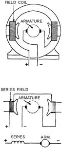
Figure 4-1. - Series ac motor. The construction of the ac series motor differs slightly from the dc series motor. Special metals,
laminations, and windings are used. They reduce losses caused by eddy currents, hysteresis, and high reactance. Dc
power can be used to drive an ac series motor efficiently, but the opposite is not true. The
characteristics of a series ac motor are similar to those of a series dc motor. It is a varying-speed machine. It
has low speeds for large loads and high speeds for light loads. The starting torque is very
4-2
high. Series motors are used for driving fans, electric drills, and other small appliances. Since the
series ac motor has the same general characteristics as the series dc motor, a series motor has been designed that
can operate both on ac and dc. This ac/dc motor is called a universal motor. It finds wide use in small electric
appliances. Universal motors operate at lower efficiency than either the ac or dc series motor. They are built in
small sizes only. Universal motors do not operate on polyphase ac power. Q2. Series motors are
generally used to operate what type of equipment? Q3. Why are series motors sometimes called universal motors? ROTATING Magnetic FIELDS The principle of rotating magnetic fields is the key to the operation of most ac motors. Both synchronous and
induction types of motors rely on rotating magnetic fields in their stators to cause their rotors to turn.
The idea is simple. a magnetic field in a stator can be made to rotate electrically, around and around. Another
magnetic field in the rotor can be made to chase it by being attracted and repelled by the stator field. Because
the rotor is free to turn, it follows the rotating magnetic field in the stator. Let's see how it is done.
Rotating magnetic fields may be set up in two-phase or three-phase machines. To establish a rotating magnetic
field in a motor stator, the number of pole pairs must be the same as (or a multiple of) the number of phases in
the applied voltage. The poles must then be displaced from each other by an angle equal to the phase angle between
the individual phases of the applied voltage. Q4. What determines the number of field poles required to
establish a rotating magnetic field in a multiphase motor stator? TWO-Phase ROTATING Magnetic
FIELD
a rotating magnetic field is probably most easily seen in a two-phase stator. The stator of a two- phase induction
motor is made up of two windings (or a multiple of two). They are placed at right angles to each other around the
stator. The simplified drawing in figure 4-2 illustrates a two-phase stator.
4-3
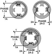
Figure 4-2. - Two-phase motor stator. If the voltages applied to phases 1-1A and 2-2A are 90º out of phase, the currents that flow in the
phases are displaced from each other by 90º . Since the magnetic fields generated in the coils are in phase with
their respective currents, the magnetic fields are also 90º out of phase with each other. These two
out-of-phase magnetic fields, whose coil axes are at right angles to each other, add together at every instant
during their cycle. They produce a resultant field that rotates one revolution for each cycle of ac. To
analyze the rotating magnetic field in a two-phase stator, refer to figure 4-3. The arrow represents the rotor.
For each point set up on the voltage chart, consider that current flows in a direction that will cause the
magnetic polarity indicated at each pole piece. Note that from one point to the next, the polarities are rotating
from one pole to the next in a clockwise manner. One complete cycle of input voltage produces a 360-degree
rotation of the pole polarities. Let's see how this result is obtained.
4-4
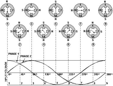
Figure 4-3. - Two-phase rotating field. The waveforms in figure 4-3 are of the two input phases, displaced 90º because of the way they were
generated in a two-phase alternator. The waveforms are numbered to match their associated phase. Although not
shown in this figure, the windings for the poles 1-1A and 2-2A would be as shown in the previous figure. At
position 1, the current flow and magnetic field in winding 1-1A is at maximum (because the phase voltage is
maximum). The current flow and magnetic field in winding 2-2A is zero (because the phase voltage is zero). The
resultant magnetic field is therefore in the direction of the 1-1A axis. At the 45-degree point (position 2), the
resultant magnetic field lies midway between windings 1-1A and 2-2A. The coil currents and magnetic fields are
equal in strength. At 90º (position 3), the magnetic field in winding 1-1A is zero. The magnetic field in winding
2-2A is at maximum. Now the resultant magnetic field lies along the axis of the 2-2A winding as shown. The
resultant magnetic field has rotated clockwise through 90º to get from position 1 to position 3. When the
two-phase voltages have completed one full cycle (position 9), the resultant magnetic field has rotated through
360º . Thus, by placing two windings at right angles to each other and exciting these windings with voltages 90º
out of phase, a rotating magnetic field results.
Two-phase motors are rarely used except in special-purpose equipment. They are discussed here to aid in
understanding rotating fields. You will, however, encounter many single-phase and three-phase motors.
Q5. What is the angular displacement between field poles in a two-phase motor stator?
4-5
THREE-Phase ROTATING FIELDS The three-phase induction motor also operates on
the principle of a rotating magnetic field. The following discussion shows how the stator windings can be
connected to a three-phase ac input and have a resultant magnetic field that rotates. Figure 4-4, views
A-C show the individual windings for each phase. Figure 4-4, view D, shows how the three phases are tied together
in a Y-connected stator. The dot in each diagram indicates the common point of the Y-connection. You can see that
the individual phase windings are equally spaced around the stator. This places the windings 120º apart.
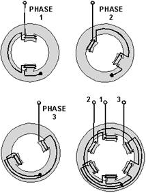
Figure 4-4. - Three-phase, Y-connected stator. The three-phase input voltage to the stator of figure 4-4 is shown in the graph of figure 4-5. use the
left-hand rule for determining the electromagnetic polarity of the poles at any given instant. In applying the
rule to the coils in figure 4-4, consider that current flows toward the terminal numbers for positive voltages,
and away from the terminal numbers for negative voltages.
4-6
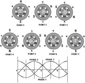
Figure 4-5. - Three-phase rotating-field polarities and input voltages. The results of this analysis are shown for voltage points 1 through 7 in figure 4-5. At point 1, the
magnetic field in coils 1-1A is maximum with polarities as shown. At the same time, negative voltages are being
felt in the 2-2A and 3-3A windings. These create weaker magnetic fields, which tend to aid the 1-1A field. At
point 2, maximum negative voltage is being felt in the 3-3A windings. This creates a strong magnetic field which,
in turn, is aided by the weaker fields in 1-1A and 2-2A. As each point on the voltage graph is analyzed, it can be
seen that the resultant magnetic field is rotating in a clockwise direction. When the three-phase voltage
completes one full cycle (point 7), the magnetic field has rotated through 360º . Q6. What is the major
difference between a two-phase and a three-phase stator? ROTOR BEHAVIOR IN a ROTATING FIELD
For purposes of explaining rotor movement, let's assume that we can place a bar magnet in the center of the stator
diagrams of figure 4-5. We'll mount this magnet so that it is free to rotate in this area. Let's also assume that
the bar magnet is aligned so that at point 1 its south pole is opposite the large N of the stator field.
You can see that this alignment is natural. Unlike poles attract, and the two fields are aligned so that they are
attracting. Now, go from point 1 through point 7. As before, the stator field rotates clockwise. The bar magnet,
free to move, will follow the stator field, because the attraction between the two fields
4-7
continues to exist. a shaft running through the pivot point of the bar magnet would rotate at the same
speed as the rotating field. This speed is known as synchronous speed. The shaft represents the shaft of an
operating motor to which the load is attached. Remember, this explanation is an oversimplification. It is
meant to show how a rotating field can cause mechanical rotation of a shaft. Such an arrangement would work, but
it is not used. There are limitations to a permanent magnet rotor. Practical motors use other methods, as we shall
see in the next paragraphs.
SYNCHRONOUS MOTORS The construction of the synchronous motors is essentially the same as the construction of the salient-
pole alternator. In fact, such an alternator may be run as an ac motor. It is similar to the drawing in figure
4-6. Synchronous motors have the characteristic of constant speed between no load and full load. They are capable
of correcting the low power factor of an inductive load when they are operated under certain conditions. They are
often used to drive dc generators. Synchronous motors are designed in sizes up to thousands of horsepower. They
may be designed as either single-phase or multiphase machines. The discussion that follows is based on a
three-phase design.
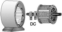
Figure 4-6. - Revolving-field synchronous motor. To understand how the synchronous motor works, assume that the application of three-phase ac power to
the stator causes a rotating magnetic field to be set up around the rotor. The rotor is energized with dc (it acts
like a bar magnet). The strong rotating magnetic field attracts the strong rotor field activated by the dc. This
results in a strong turning force on the rotor shaft. The rotor is therefore able to turn a load as it rotates in
step with the rotating magnetic field. It works this way once it's started. However, one of the
disadvantages of a synchronous motor is that it cannot be started from a standstill by applying three-phase ac
power to the stator. When ac is applied to the stator, a high-speed rotating magnetic field appears immediately.
This rotating field rushes past the rotor poles so quickly that the rotor does not have a chance to get started.
In effect, the rotor is repelled first in one direction and then the other. a synchronous motor in its purest form
has no starting torque. It has torque only when it is running at synchronous speed. A squirrel-cage type
of winding is added to the rotor of a synchronous motor to cause it to start. The squirrel cage is shown as the
outer part of the rotor in figure 4-7. It is so named because it is shaped and looks something like a turnable
squirrel cage. Simply, the windings are heavy copper bars shorted
4-8
together by copper rings. a low voltage is induced in these shorted windings by the rotating
three-phase stator field. Because of the short circuit, a relatively large current flows in the squirrel cage.
This causes a magnetic field that interacts with the rotating field of the stator. Because of the interaction, the
rotor begins to turn, following the stator field; the motor starts. We will run into squirrel cages again in other
applications, where they will be covered in more detail.
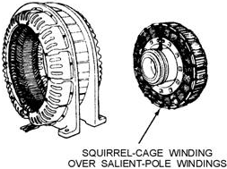
Figure 4-7. - Self-starting synchronous ac motor. To start a practical synchronous motor, the stator is energized, but the dc supply to the rotor field is
not energized. The squirrel-cage windings bring the rotor to near synchronous speed. At that point, the dc field
is energized. This locks the rotor in step with the rotating stator field. Full torque is developed, and the load
is driven. a mechanical switching device that operates on centrifugal force is often used to apply dc to the rotor
as synchronous speed is reached. The practical synchronous motor has the disadvantage of requiring a dc
exciter voltage for the rotor. This voltage may be obtained either externally or internally, depending on the
design of the motor. Q7. What requirement is the synchronous motor specifically designed to meet?
INDUCTION MOTORS The induction motor is the most commonly used type of ac motor. Its simple, rugged construction costs
relatively little to manufacture. The induction motor has a rotor that is not connected to an external source of
voltage. The induction motor derives its name from the fact that ac voltages are induced in the rotor circuit by
the rotating magnetic field of the stator. In many ways, induction in this motor is similar to the induction
between the primary and secondary windings of a transformer. Large motors and permanently mounted motors
that drive loads at fairly constant speed are often induction motors. Examples are found in washing machines,
refrigerator compressors, bench grinders, and table saws. The stator construction of the three-phase
induction motor and the three-phase synchronous motor are almost identical. However, their rotors are completely
different (see fig. 4-8). The induction rotor is made of a laminated cylinder with slots in its surface. The
windings in these slots are one of two types (shown in fig. 4-9). The most common is the squirrel-cage winding.
This entire winding is made up of
4-9
heavy copper bars connected together at each end by a metal ring made of copper or brass. No
insulation is required between the core and the bars. This is because of the very low voltages generated in the
rotor bars. The other type of winding contains actual coils placed in the rotor slots. The rotor is then called a
wound rotor.
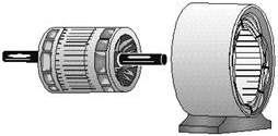
Figure 4-8. - Induction motor.
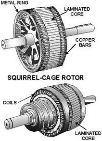
Figure 4-9. - Types of ac induction motor rotors. Regardless of the type of rotor used, the basic principle is the same. The rotating magnetic field
generated in the stator induces a magnetic field in the rotor. The two fields interact and cause the rotor to
4-10
| - |
Matter, Energy,
and Direct Current |
| - |
Alternating Current and Transformers |
| - |
Circuit Protection, Control, and Measurement |
| - |
Electrical Conductors, Wiring Techniques,
and Schematic Reading |
| - |
Generators and Motors |
| - |
Electronic Emission, Tubes, and Power Supplies |
| - |
Solid-State Devices and Power Supplies |
| - |
Amplifiers |
| - |
Wave-Generation and Wave-Shaping Circuits |
| - |
Wave Propagation, Transmission Lines, and
Antennas |
| - |
Microwave Principles |
| - |
Modulation Principles |
| - |
Introduction to Number Systems and Logic Circuits |
| - |
- Introduction to Microelectronics |
| - |
Principles of Synchros, Servos, and Gyros |
| - |
Introduction to Test Equipment |
| - |
Radio-Frequency Communications Principles |
| - |
Radar Principles |
| - |
The Technician's Handbook, Master Glossary |
| - |
Test Methods and Practices |
| - |
Introduction to Digital Computers |
| - |
Magnetic Recording |
| - |
Introduction to Fiber Optics |
| Note: Navy Electricity and Electronics Training
Series (NEETS) content is U.S. Navy property in the public domain. |
|


