|
|||||||||||||
 |
|||||||||||||
Resistive Splitting Pads
|
|||||||||||||
Designing resistive impedance-matched signal splitting networks is nowadays mostly done with the assistance of computer software. In fact, odds are pretty high that the designer either has no idea what the formulas behind the "magic" are, or at least it has been a very long time since working them with pencil and paper. There's no shame in that, though, just as there is no reason to expect someone using a cellphone must know the intricacies of the internal circuits or the network to which it is connected. We've moved past that. For those of us who still appreciate a refresher on the behind-the-scenes calculations being performed at lightning speed within the smartphone or computer, this 1951 Radio & Television News magazine article will be a welcome bit of information. Splitting PadsBy H. C. Carmichael, Consulting Engineer
Details on how various resistor combinations can be used to provide the proper matching networks. It is sometimes necessary in communication and television work to apply two alternating currents such as speech, carrier, or music currents to one channel. This may be done by means of a transformer, but owing to the electromagnetic fields and frequency losses from the transformer, this method is not always desirable, and another method using combinations of non-inductive resistances is sometimes used. This method involves the formation of resistance networks, called pads, from non-inductive resistances. In the case of 600 ohm circuits it is usual to make matching pads from 1200 to 600 ohms and to connect the 1200 ohm outputs in parallel. There is a third method, shown in Fig. 1A, using a network of standard non-inductive resistors which involves a small power loss but is less expensive than the other methods.
Fig. 1 - Circuit configurations An application of this method is shown in Fig. 1A, where it is used to connect two sources of alternating current to one channel or vice versa. For purposes of matching, it is necessary to make the values R1 R2 R3, shown in Fig. 1A, such that when channels 1 and 2 are terminated in their correct impedances (600 ohms), then channel 3 will also be 600 ohms. Fig. 1A may be simplified to the arrangement shown in Fig. 1B. Now, when two resistances, R1 and R2 are connected in parallel their joint resistance may be found by the aid of the formula:
If this formula is applied to Fig. 1B, then the joint resistance of the two paths (600 ohms and x ohms) from A to C is:
Similarly, the joint resistance of the two resistances (600 ohms and ix ohms) between Band C is:
These two joint resistance values are in series with respect to the line and thus their total resistance is:
The other resistor from A to B (x ohms) is in parallel with this combination as shown in Fig. 1C which is a further simplification of Fig. 1A. Thus, if formula (1) is applied to this circuit, then the joint resistance of the combination will be:
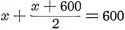
This, of course, must equal the resistance of channel 3 and thus:
This may be simplified to show that x = 1800 ohms. Figure 1D shows the resistance network to satisfy the conditions shown in Fig. 1A. Power Loss of Pad The power loss from each channel to the mixer channel resulting from the use of this pad can be calculated as follows. Assuming a voltage of 10 volts across a source of 600 ohms in channel 3, then the voltage across points A and B in Fig. 1D would be 10 volts and the voltage across points A and C would be 5 volts, as the resistance of the combined resistor AC is equal to the combined resistor CB. The power loss equals:
and if the information supplied in the data is substituted in this formula, then: - Power loss = Delta to Star Conversion Another connection called the "star" connection has the advantage over the "delta" connection of being a simpler combination, and the delta circuit shown in Figs. 1D and 1E may be converted to the star or "Y" connection shown in Fig. 1F. Now if these circuits are to be equivalent, then the resistance between points AB, BC, and CA in Figs. 1E and 1F must be similar. At a glance if may be clear that in Fig. 1F the resistance from A to O will equal 600 ohms, the resistance O to B will also equal 600 ohms, making A to B equal to 1200 ohms as required. It may be mathematically proved, however, that: -
For example, to convert the delta formation in Fig. 1D to an equivalent star or "Y" formation, then: -
and likewise, RB and RC will be equal to 600 ohms respectively. The equivalent star or "Y" connection would be then as shown in Fig. 1G. Practical Application This type of network has practical application in circuits such as the one shown in Fig. 1L where three balanced channels are connected together via the star connection. This circuit enables two sources of alternating current to be fed into one channel or one source of alternating current to be split into two channels. Another practical application of the star pad is shown in Fig. 1M where the output from an amplifier may be: - (a) Disconnected from both channels, (b) Connected to both channels, or (c) Connected to either channel. This arrangement may be also used to mix the output of two amplifiers into the one channel. There are many and varied applications of this simple circuit arrangement but it must be remembered that the loss of 6.02 decibel is a disadvantage. The use of standard 600 ohm non-inductively wound bobbins considerably simplifies the construction of the pads and carbon resistors of suitable value may also be used. Matching with Series Resistors Another method of matching is by the use of series resistances in each branch of individual circuits as shown in Fig. 1J. In this circuit, channels 2 and 3 are assumed to be terminated in their correct impedances, and thus channel 1 must look like 600 ohms. Now the circuit shown in Fig. 1J may be simplified to that shown in Fig. 1I, and Fig. 1I, in turn, simplified to that shown in Fig. 1H. The joint resistance of two equal resistances in parallel may be found by dividing the resistance of one by the number of resistances connected in parallel, and in the case of the two equal resistances shown in Fig. 1H, the joint resistance will be: -
The impedance of the network shown in Fig. 1H must match the impedance of channel 1 (that is, 600 ohms) and thus: -
therefore x = 200 ohms. This value of 200 ohms represents the sum of the values of both resistors in each branch of the network and thus each resistor will be: -
The completed circuit will then be as shown in Fig. 1K. This circuit has an approximate loss of 4.44 decibels in each channel which, however, is not a very serious disadvantage. The same circuit arrangements may be used with this method as shown in the previous circuits, and, while not as simple as these, it is nevertheless simpler than the standard matching pad. Another feature of the split pad is that the pad does not affect the frequency response, provided that non-inductive resistors are used. The author wishes to thank Mr. Charles Smith for his assistance in the mathematical development of various equations. |
|||||||||||||
 |
|||||||||||||
|
|||||||||||||


 = 20 log 2 = 6.02 decibel

 = 600 Ohms
 or 100 Ohms
|
||||||||||||||||||||||||||||||||||||


