|
May 1931 Radio-Craft
 [Table of Contents] [Table of Contents]
Wax nostalgic about and learn from the history of early electronics.
See articles from Radio-Craft,
published 1929 - 1953. All copyrights are hereby acknowledged.
|
Analog and most digital multimeters
rely on precision resistors for scaling the input voltage or current to keep it
within the safe operational range of the meter movement or analog-to-digital converter
circuit. Resistance value selection is a relatively simple matter of series and/or
parallel combinations and their resulting divisions of voltages and/or currents.
When this article appeared in a 1931 issue of Radio-Craft magazine, the
whole concept of electrical circuit design was entirely new to most people, including
shunts and multipliers for meter scales. The International Rectifier Company
(IRC) article gives a handy rule of thumb for setting resistor values when
considering the resistance of the meter movement coil. There is a nice table of resistor values
provided, but I was a little disappointed to find that not a single equation is
given for calculating custom values.
Determining Meter Shunts and Multipliers
International Rectifier Company
Investment in a milliammeter or microammeter may be made to pay greater dividends,
in the form of diversified applications, by conversion to a multi-range volt-meter,
Likewise, the usual voltmeter can be readily converted to a multi-range volt-meter.

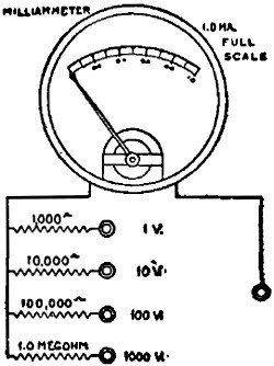
Fig. 1 - The ordinary 0-1 milliammeter, as shown, with the
series resistors becomes a multi-scale voltmeter. The resistor values should, theoretically,
be lessened by the resistance of the meter's moving element but, except on the 1-volt
scale, this would make too trifling of a difference to be read.

Fig. 2 - The same principle is applied to a standard voltmeters,
except that the first series resistors is already provided.
The connections shown in Fig. 1 are intended for the conversion of
microammeters and milliammeters into voltmeters. Those shown in Fig. 2 are for
the conversion of a 100-volt, high-resistance meter to a multi-range voltmeter,
by means of a number of precision wire-wound resistors which serve as voltmeter
multipliers. In using resistors of this type as voltmeter multipliers, it is
essential to know the internal resistance of the voltmeter, expressed in ohms
per volt. Then multiply the full-scale reading of the voltmeter by the number of
ohms per volt; insert a similar resistance
value in series with the instrument, and the added resistor will double the effective
scale reading.
The moving element of voltmeters may be used, in conjunction with a multiplier,
to obtain lower ranges than those for which the meter was originally made, with
a great saving over the cost of a new meter. The new multiplier or multipliers must
be directly connected to the moving-element leads.
The resistance of the multiplier can be computed by the following formula: multiply
the ohms per volt by the full-scale deflection; then the product by the desired
multiplier ratio; and subtract the resistance of the moving-element. But since the
resistance of most moving-elements is low (say 40 ohms to 0.1 ohm) it may be neglected
except when the computed multiplier resistance is only fifty (or fewer) times the
order of magnitude of the resistance of the moving-element.
The accompanying chart gives the total resistance required to change microammeters
and milliammeters into instruments for accurately measuring voltage, Since the resistance
of most microammeters and milliammeters is very low, that is, 40 ohms or much less,
these values may be used for the multiplying resistors. The error in this assumption
is the resistance of the instrument divided by the resistance given in the table;
which, in most cases, is very much less than the error in most calibrations. The
maximum error, other than the above, is the sum of the error of the moving-element
and the error in the resistance value used. A moving element that is accurate to
2 percent would never become more accurate, no matter how accurate the multiplier
was made. On the other hand, if a high degree of accuracy is wanted and the moving
element was designed for that type of work, a very accurate multiplier must be used.
If closer accuracies that 1 percent are required, resistors must be better than
1/2 percent.
Fortunately, wire-wound resistors of an accuracy of 1 percent and closer are
now available commercially, as contrasted with the wider tolerances of resistors
of the past. Furthermore, these resistor are thoroughly seasoned. These perfected
wire-wound resistors now make it possible to convert meters into multi-range instruments
with every assurance of accurate readings.

Posted April 11, 2022
(updated from original post on 12/16/2014)
|


