|
Admittedly, I did not do any
follow-up research on this, but there is reason to believe that prior to this
1944 Radio
News magazine article, there was not a general agreement on what formula to use
for thermal noise in an electrical system. Here is a statement made by author S.J. Mallory,
"At first, however, there was no general agreement concerning the magnitude of this
basic Johnson noise power level. Some engineers used the quantity KTB, others used
2KTB and still others used 4KTB." We of course all use KTB nowadays for thermal
noise power - aka Johnson noise. It's a good read on the subject of sources that
determine the noise floor of a system. There's also this kind of
Johnson noise.
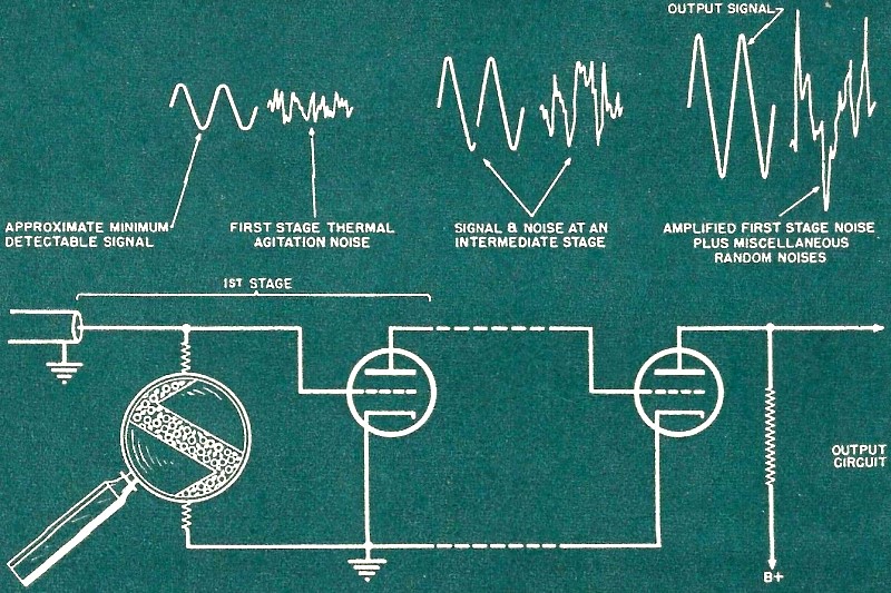
Noise of Thermal Agitation
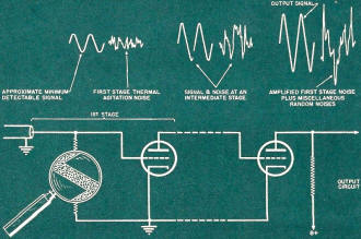
Fig. 1 - Minimum detectable incoming signal must have rms value
several limes first stage thermal noise so output may be intelligible. Magnified
resistor shows random electron motion.
By S. J. Mallory
Calculation of the "Johnson noise" thermal noise voltage developed in the input
resistor of a high-gain amplifier.
In 1928, J. B. Johnson published an article describing an ever-present source
of noise in electrical conductors. The noise is caused by free electrons moving
about in the conductor. This discovery is of great importance in the field of communications
because it is a factor which provides as a definite barrier, the lower limit of
detectable signal. Signals of lower level than this basic "Johnson Noise" are lost
in the noise.
There are also other noise sources prevalent in receivers, for example, the various
noises occurring in vacuum tubes, but first circuit Johnson noise is usually predominant
in well constructed receivers. If the first tube input resistance is small, it is
possible for vacuum tube noise to exceed first circuit noise. These other miscellaneous
noises are added to the basic Johnson noise to increase the level of the minimum
detectable signal. The total noise across the output terminals of a receiver, converter
or i.f. amplifier is a measure of the performance of the unit because ordinarily
any signal of a level lower than this output noise level cannot be distinguished.
Thermal Noise Voltage
The noise in a simple resistance made up from a length of conductor will be discussed
first. The conductivity of metals is a result of the presence of free electrons
which move about at a velocity that depends on their temperature. At any instant
there are more electrons moving in one direction than in any other; this produces
a difference of potential across the conductor ends. This voltage varies from instant
to instant in accordance with the predominant motion of the electrons. The magnitude
of the mean square voltage developed per cycle of band width is directly proportional
to the absolute temperature of the resistance and to the magnitude of the resistance
involved. The voltage is independent of the size, shape and material of the conductor.
The existence of this random voltage is evidenced as noise in the first circuits
of amplifiers and in other circuit elements which normally operate at low signal
levels. The noise is called the noise of thermal agitation, or Johnson noise, after
its discoverer.
Typical receiver with high-gain i.f. amplifier. First stage noise
must be considered in design.
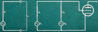
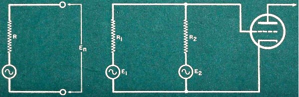
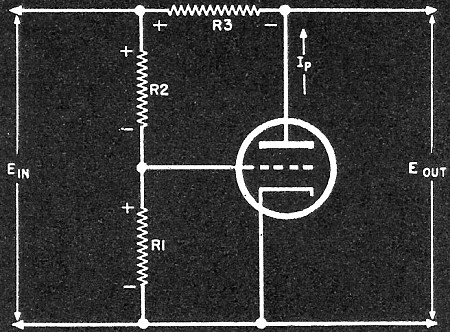
Fig. 2 - (A) Equivalent circuit for calculating Johnson noise.
(B) Source of noise, with internal impedance R1 working into load resistance
R2 input resistance of amplifier.
Fig. 3 - Did not appear in the magazine article.
The noise of thermal agitation is quite uniformly distributed over the entire
frequency spectrum from zero to frequencies much higher than normally used for radio.
Therefore, a 5000 cycle band lying in the audio range would contain as much Johnson
noise power as a 5000 cycle band in the microwave region, provided that the resistance
is constant over the frequency band under consideration.
Let R in Fig. 2(A) be the internal resistance of a signal generator. Thus, if
R is constant over the frequency bandwidth B, J. B. Johnson found that the square
of the effective value of the noise voltage components over the frequency band is:
E2 = 4KTRB ................ (1)
where,
K = 1.38 X 10⁻²³, Boltzmann's constant.
T = Absolute temperature, deg. Kelvin.
R = Resistance in ohms.
B = The effective bandwidth in cycles per second. The effective bandwidth may
be determined as follows: An energy response curve (output current squared vs. frequency)
is plotted for the amplifier under consideration. The total area under the curve
is divided by the height of the curve at resonance, thus obtaining the width of
an equivalent rectangle. This width is the effective bandwidth in cycles per second.2
A temperature of 290° K, corresponding to 17° C. or about 63° F.,
is frequently used.
Noise Power Reference Level
Other noises in amplifiers may be controlled to a great extent by design considerations,
but it became recognized that the noise of thermal agitation was omnipresent. After
all other inherent noises were eliminated, Johnson noise remained and it seems determined
to stay as long as conductors are used.
As the use of extremely high-gain i.f. amplifiers became more widespread, Johnson
noise became a more widely recognized factor in amplifier design. Gradually, the
ratings of high-gain amplifiers have become known in terms of noise performance.
The noise power output level is quoted as a certain number of db. above the power
level of Johnson noise. At first, however, there was no general agreement concerning
the magnitude of this basic Johnson noise power level. Some engineers used the quantity
KTB, others used 2KTB and still others used 4KTB. One engineer using the 4KTB base
might rate an amplifier as having a noise performance of 11 db. above theoretical,
a second engineer using the 2KTB base would rate the identical equipment as having
a noise figure of 8 db., and the third engineer might consider 5 db. the correct
value.
2KTB is the maximum noise power available in a load resistance R when it is used
to terminate a network of equal resistance and temperature. Under certain conditions
when the load resistance is different than the generator resistance, the thermal
noise level may be less than 2KTB. To avoid using a reference level which was not
an ideal condition and to avoid the confusion prevalent with the existence of several
different reference levels, in 1941 it was generally agreed upon that KTB should
be used as the basis for determining the noise performance of receivers.
First Stage Noise Power

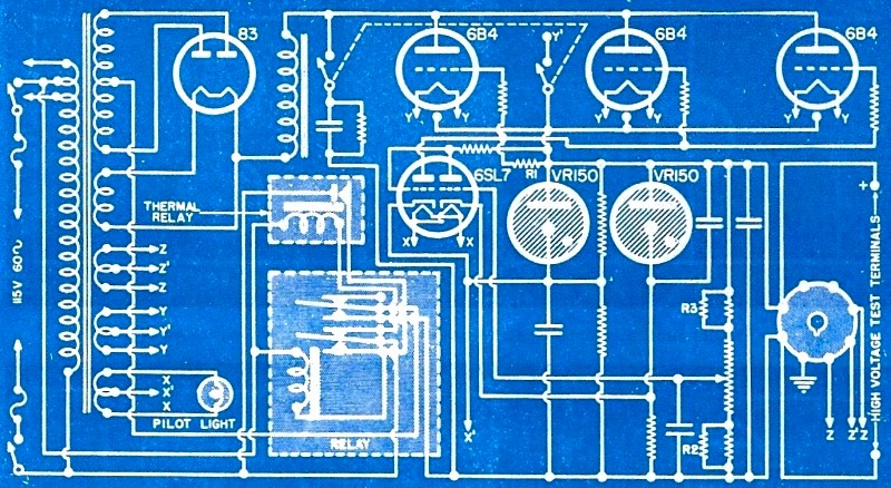
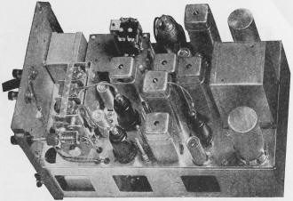
Fig. 4 - Electronically-regulated power supply. manufactured
by the Communication Measurements Lab. The output voltage variations are amplified
twice before being applied to 6B4 tubes. Voltage range may be adjusted by changing
R2 and R3.
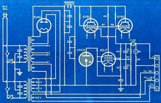
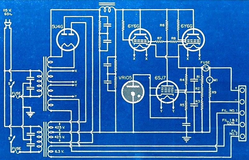
Fig. 5 - A commercial application of the circuit given in Fig.
8. A power supply employing this circuit was designed and manufactured by the Harvey
Radio Labs., Inc.
In Fig. 2 (B) R1 is considered to be the internal resistance of a
signal source, and R2 the input resistance of the first tube of a high
gain amplifier. (In such an amplifier the gain will raise the level of the input
signal and noise to a point where it will override the inherent tube noise and other
noise sources within the amplifier.) E1 and E2 are the sources
of noise in R1 and R2 respectively.
In order to determine the effect of thermal noise on the first circuit of an
amplifier, the value of the maximum available noise power in R2 must
be found as it is this noise power in the first circuit input resistance that is
a measure of the output noise of the amplifier. The noise voltage generated in R1
over a bandwidth B is:
E12 = 4KT1BR1 ..................
(2)
Neglecting for the moment the noise power generated in R2, the maximum
noise power available from R1 is that power which would be absorbed by
a matched output circuit. Therefore, when R1 = R2
P01 = E12/4R1 = KT1B .......
(3) watts noise power delivered to R2 by R1. But, when the
temperatures T1 and T2 of R1 and R2
respectively are equal, then R2 contributes a like amount of noise power
to itself. Therefore the total noise power in R2 is:
PNM = P01 + P02 = 2KTB .... (4)
Since a major portion of communications circuits are designed around the premise
that connected circuits shall have matched impedances, the quantity 2KTB was originally
used as the basic minimum amount of noise in an ideal receiver. An ideal receiver
is one with negligible output noise when the input is shorted. Later it was found
that a judicious mismatch would result in a noise power somewhat less than 2KTB.
It was concluded that theoretically the ultimate in mismatch would result in a minimum
noise power of KTB. But since this ultimate in mismatch occurs when R2
of Fig. 2(B) is infinite, the minimum noise, KTB, has never been realized. The quantity
KTB is the thermal noise in the first circuit of an ideal receiver.
To compare the noise in a circuit under matched conditions with the noise under
mismatched conditions, the signal-to-noise ratios for these two conditions is calculated.
For the matched case in Fig. 3, let R1 = R2. The signal power
in R2 is:
PS = ES2/4R2 ............ (5)
The noise power is given by (4).
Therefore,  ......... (6) ......... (6)
the signal-to-noise power ratio for the matched case.
For the mismatched case it is assumed that R2 is very large, so large
in fact that there is no appreciable voltage drop across R1. It is also
assumed then that the voltages appearing across R2 are the signal voltage
ES and the noise voltage √(4KTBR2). The signal power
in R2 will be:
PS = ES2/R2 ................ (7)
and the noise power,
PN = (4KTBR2)/R2 ........ (8)
Therefore, the signal-to-noise power ratio for the ultimate of mismatch will
be:
PS/PN = ES2/(4KTBR2) ..........
(9)
The signal-to-noise ratio in case of voltage-regulator tube, VR 105-30. Resistor
R2 is made variable in order that the output voltage may be placed at
the desired value. The position of this setting, however, does not in any way interfere
with the operation of the stabilizing unit. Condenser C aids the regulating action
when changes in Eout, appear rapidly.
The first commercial power supply schematic is shown in Fig. 5. This circuit
is much the same as that given in Fig. 8. The 6SJ7 is the sharp cut-off pentode
tube that amplifies the output voltage fluctuations applied at its grid through
the series combination of R1, R2, and R3. The setting
of R2 enables the operator to vary the output voltage between 200 and
300 volts. R1 and R5 provide the proper screen-grid voltage
to the 6SJ7.
Any variations in the plate current of the pentode cause the voltage across R.
to vary. Since this resistor is connected to the grids of the parallel 6Y6's, their
grid voltage will change and thus control will be had over the output current and
voltage. R7 and R8 are used to isolate the two 6Y6's from
each other and prevent any tendency toward oscillation. Meter M1 and
R9 form a voltmeter to keep constant track of the output voltage. The
rest of the circuit is similar to what has been described already and requires no
further explanation. Notice how well fused the set is and the use of separate switches
for the plate and filament transformers.
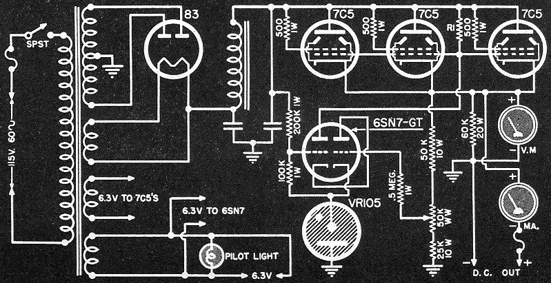
The next commercial circuit (Fig. 7) has a slight variation over the foregoing
power supplies. Here all voltage fluctuations are applied to the grid of one of
the triodes of the 6SN7GT tube. After amplification, the variations are sent through
the other triode section of the 6SN7 and on to the 500,000 ohm resistor, R1
connected between the control grid and plate of each of the three 7C5's in parallel.
From here on the action differs in no way from the explanation given previously
for
40 either one series tube or two in parallel. With the three 7C5's, a maximum
current of 250 milliamperes may be drawn from the supply at a plate voltage of 200
to 400 volts. It is to be noticed here that input voltage changes in the a.c. line
immediately affect the grid of one triode section of the 6SN7 and this acts in conjunction
with any output variations that affect the other triode. The result is better regulation
than if the line voltage instabilities were left to affect the output voltage and
then ironed out.
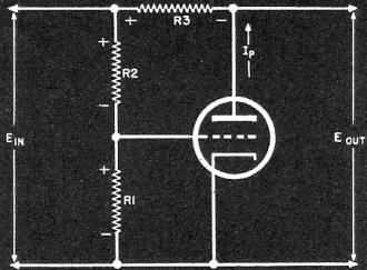
Fig. 6 - A vacuum-tube voltage regulator circuit using the Gm
of the tube as its basis of operation.

Fig. 7 - Power supply manufactured by Technical Apparatus Co.
employs a double triode to amplify input and output variations. Unit supplies 200-400
volts d.c. at 40 watts.
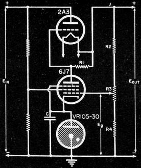
Fig. 8 - Improved voltage regulator employing the same basic
circuit as Fig. 2.
For the final commercial diagram, Fig. 4, we again find a double triode (a 6SL7),
this time used differently, however. The output voltage of one triode is fed directly
to the grid of the other triode and from thence to the 6B4G regulator tubes. This
double amplification gives rise to a very sensitive arrangement whereby even small
amounts of ripple may be eliminated. The duo-triode used in the previous power supply
described above did not have the output of one amplified by the other. Rather both
were connected into different circuits (the output and the input) and their voltage
changes worked in conjunction with each other. In the present setup, both triodes
deal mostly with variations in Eout only, and they are unable to counteract
input line changes directly. Resistor R1 transmits the amplified regulating
voltages to the grids of the 6B4 tubes. Note that direct coupling is used throughout
most of these amplifiers. This insures that even slow changes in output voltage
are effective in this regulating action. Condenser-coupled amplifiers would not
be suitable because of their poor low-frequency response.
The above power units are indicative of what may be expected in present day electronically-regulated
supplies. Each unit is now being sold in the radio market. Now let us see how they
may be designed. Fig. 8 will be used as illustration for the procedure.
The first point that must be decided concerns the amounts of current and voltage
that the power supply will be called upon to deliver. A thirty per cent tolerance
should be allowed between the required load and that which the unit can supply.
This will permit a comfortable leeway and prevent overheating of the power transformer.
With the current and voltage values determined, the proper electrolytic condensers,
filter choke (or chokes) and power transformer can then be chosen. These are connected
as shown in Fig. 5. One pi filter section will work satisfactorily since the degenerative
amplifier will remove any remaining ripple by its regulator action.
The design of the regulator section is attacked next. The choice of the series
tube (or tubes) will depend on the amount of current that the power supply will
have to supply. Generally, a power-amplifier tube is used because it will allow
greater plate dissipation and current flow than ordinary amplifier tubes. If one
tube should prove insufficient, then several may be placed in parallel. Experimentally,
the amount of wattage being dissipated in the tube may be determined by connecting
it into the circuit and measuring the voltage dropped across it. This figure, multiplied
by the current through the tube, gives the wattage in the tube. The foregoing generally
must be done because the desired information is not obtainable from tube manufacturers.
For the feedback tube, a sharp cut-off pentode is desirable, this giving better
and more clear-cut control than the remote cut-off pentodes. A glance through the
tube manual will reveal several suitable tubes. The pentode, however, is not the
only possible tube. This was made clear in two of the commercial circuits just examined.
Here duo-triodes were used quite successfully. The main purpose of the feedback
amplifier is to have large variations in plate current from small changes in grid
voltages. The greater this action, the more sensitive the circuit will be to output
voltage variations. The amplifier (or amplifiers) does not contain any condenser
coupling, this automatically reducing low-frequency changes from having the effect
they should have. Direct coupling is used throughout.
The remaining problem of designing R2 R3, and R4
is decided in the following manner. Eg, that portion of the output voltage
applied to the grid of the 6J7, is related to Eout by this simple equation:
where: Rx is the bottom portion of R3 between the center
arm and R4. This voltage, when subtracted from the 105 volts of the VR
tube, gives the actual volt-age on the grid of the 6J7. Generally, this value is
such as to keep the grid negative with respect to the cathode. In the present case,
this would mean that Eg would have a value less than the VR's 105 volts.
A characteristic chart of the tube used will indicate quickly the amount of variation
desirable. From this value, the proportion that R3 will be of the total
resistance of R2 plus R3, plus R4 can be easily
computed. R2 and R4 are placed' on either side of R3
to insure that the voltage applied to the 6J7 will be below a certain maximum value
and above a certain minimum.
When actually constructed, these units are rather large in size. A roomy chassis
will insure good ventilation with adequate space between components, especially
transformers and power chokes. A well-designed panel, such as shown in the photograph
will aid the operator to quickly reach the controls easily and safely. Any radio
manufacturer will confirm the fact that good layout is just as important as circuit
design, and it is always given a great deal of thought. Note that even fuses are
placed on the panel, each possible of quick replacement. For the man who uses these
units every day, these little considerations may determine the choice of one unit
over another.
Posted December 12, 2023
(updated from original
post on 11/1/2019)
|