|
After discussing the technical
benefits of single-sideband (SSB) amplitude modulated (AM) commercial transmission
versus double-sideband + carrier standard AM, author Jack Brown concludes with a
chart plotting the relative cost of each method versus output power. The result:
Transmitters with less than 100 watts output the initial equipment cost of a single-sideband
transmitter is greater than its standard AM counterpart. My guess is that with today's
equipment the chart would look a lot different, and there may be no dollar cost
benefit either way from a hardware perspective. The benefit of SSB of course is
in spectrum efficiency and, especially for very high powers, operational cost savings
on electricity bills. Even so, commercial AM broadcast radio stations in the U.S.
still transmit using the fundamental double-sideband + carrier modulation format.
That's both lower and upper sidebands and a carrier. The motivation is and
has always been for
backward compatibility to old receivers, a perceivable higher quality (than SSB)
of sound, and it facilitates stereo AM schemes.
See Part 2 in the June 1956 issue of Radio & Television News.
Commercial Aspects of Single-Sideband
 By Jack N. Brown By Jack N. Brown
Engr., Barker & Williamson
Part 1. A three-part series - although directed to the commercial services who
have or may go to SSB operation, most of the technical aspects of this series will
also be of interest to radio amateurs.
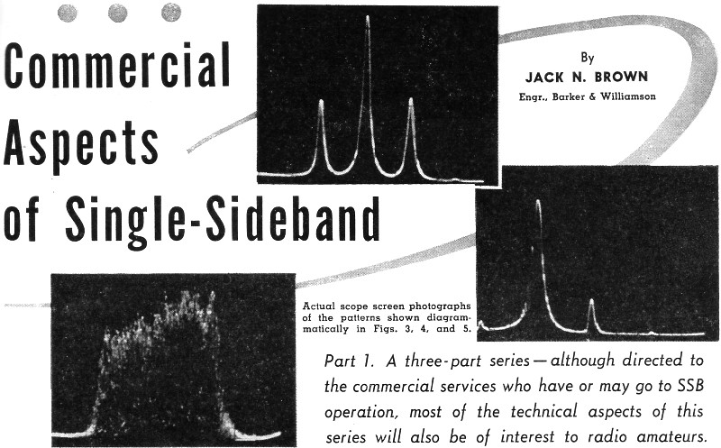
Actual scope screen photographs of the patterns shown diagrammatically in Figs.
3, 4, and 5.
It is becoming increasingly apparent that single-sideband is destined for more
widespread use in the commercial services. In view of the recent FCC action in Docket
11513, it would appear that single-sideband will eventually become mandatory for
all commercial services below 25 mc. The reason for the recent FCC action is, of
course, spectrum conservation. There are other advantages to be gained by changing
to single-sideband but these will be outlined later.
Historical Background
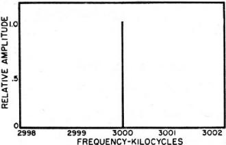
Fig. 1 - A spectrum representation of a continuously keyed (3000
kc.) unmodulated carrier. Note that there are no extra sidebands present and the
carrier "width" is infinitely thin. See discussion in text.

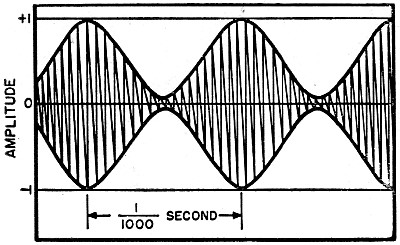
Fig. 2 - Sketch of an oscilloscope trace made by a 100% modulated
AM transmitter when modulated by a tone of 1000 cps.
Single-sideband for radiotelephone has been in fairly common use since the mid-1920's.
The first commercial application of this technique was a joint experiment by RCA
and A. T. & T. on a circuit that spanned the Atlantic from New York to London.
Prior to that time single-sideband had been used only on carrier-current telephone
circuits for landline service. It soon became apparent that the system offered decided
advantages over the previously attempted double-sideband AM circuits. At that time
the generation of single-sideband was a fairly complex matter and required some
unusual techniques for the radio art at that stage of its development. From 1927
until World War II the only commercial use that was made of single-sideband was
by American Telephone & Telegraph Company in its transoceanic commercial telephone
service. There is considerable material in the literature1, 2 justifying
the use of single-sideband rather than double-sideband AM transmission.
With U. S. entry into World War II it became increasingly apparent to the military
services that additional radio channels were required. The cooperation of A. T. &
T. was enlisted in furnishing single-sideband circuits for radiotelephone as well
as multi-channel radio teletype. The first circuits used by the military were leased
from A. T. & T. but as the war progressed the military services themselves procured
single-sideband equipment and trained teams of military personnel to operate it.
Today the bulk of military point-to-point communication is handled by single-sideband
with as many as two channels of radiotelephone transmitted on one sideband and up
to twelve teletype circuits handled on the other sideband. Thus a total of fourteen
communication circuits is available between two given points from a single transmitter.
The economy of such a method is evident and the actual operational success of this
technique is daily becoming more apparent. Since World War II the military services
have continued their expansion of single-sideband circuits.
The major growth in single-sideband activity has, of course, been among the radio
amateurs of this country. Circuit developments since World War II indicate that
a single-sideband signal can be generated with simpler equipment than heretofore
thought possible. The principal drawback to single-sideband prior to World War II
was the difficulty in maintaining the frequency stability required for such a system.
Recent technical developments leading to improved oscillator stability, the availability
of better and higher frequency filters, wide-band audio and radio-frequency phase-shift
networks, and newer tubes make single-sideband generation and transmission more
practical. It is the intent of the author to outline for the prospective commercial
user of single-sideband just what the system has to offer, its advantages and disadvantages,
and the economics of changing from an existing AM system to a SSB system.
Nature of Single-Sideband
To understand single-sideband it is desirable to start with something known,
i.e., an amplitude-modulated, double-sideband signal. One step still further toward
the elementary would be to consider an unkeyed c.w. carrier at the input of the
receiver. This unkeyed, unmodulated c.w. signal occupies no bandwidth whatever.
It can be visualized as an infinitely thin line drawn at a specific frequency where
a plot of frequency along a horizontal axis is one dimension and the height of the
carrier is merely a measure of its amplitude. See Fig. 1. If anything at all is
done to the c.w. carrier e.g., if it is interrupted at some finite keying rate,
modulated with either AM, FM, or phase modulation, there are other radio-frequency
components present besides that of the carrier itself. If an oscilloscope is connected
to the output of the transmitter, the pattern shown in Fig. 2 would be seen for
a single frequency fed into audio stages of the transmitter.
It should be noted that 100% modulation occurs when the negative peaks of modulation
meet at the center line of the pattern. If we were to look at the signal on a spectrum
analysis basis as was just done with the c.w. carrier we would see the following:
The carrier would be present at its original frequency; however, there would be
two other radio frequency signals present at the output of the transmitter which
are directly dependent upon the audio modulation frequency fed into the transmitter.
If the audio frequency fed into the transmitter is 1000 cps, the two additional
signals present at the transmitter output would be exactly 1000 cycles above and
below that of the carrier frequency. If the audio modulation frequency is changed
from 1000 cycles to 3000 cycles, the two sideband signals would move from 1000 cycles
either side of the carrier frequency to 3000 cycles either side of the carrier frequency.
Similarly, if the audio frequency is changed to 300 cycles, the sideband signals
would move closer in frequency to that of the carrier, i.e., to within 300 cycles
of the carrier. Thus it can be seen that for each single audio frequency fed into
the microphone of an amplitude-modulated transmitter there are two sideband signals
present at the output of the transmitter, each carrying the exact same intelligence,
namely, that of the distance by which it is separated from the carrier signal and
its relative amplitude.
When the signal appears at the second detector of the communication receiver
the carrier frequency is heterodyned with the two sideband signals. The two separate,
but identical, audio signals are recovered and combined in the audio system of the
receiver.
These two signals add in-phase to produce intelligible audio at the receiver
loudspeaker terminals. Fig. 3 shows the AM signal as obtained from a Panoramic Radio
Products, Inc., spectrum analyzer, Model SB-8A. This shows the two sideband signals
1000 cycles either side of the carrier. It will be noted that the carrier voltage
is two times greater than that of each individual sideband signal if the vertical
scale is a linear plot of voltage. Thus it can be seen that for a 100-watt AM transmitter
the maximum power that can be realized in either sideband is 25 watts peak. This
nets an effective 50 watts peak power when the two sidebands are recovered at the
receiver. The carrier, meanwhile, has been transmitted along with the two sideband
signals and has accomplished only one thing, that is, demodulating or heterodyning
the sideband intelligence back into the audio-frequency range. The carrier itself
has contributed nothing to the actual intelligence transmitted. It has neither "carried"
nor enhanced the intelligence transmitted in any way. Thus for an average power
of 100 watts and an intermittent power of 150 watts being transmitted by our hypothetical
AM transmitter we have, at the distant receiving station, a signal attributed to
only 50 watts of the actual transmitted power. This would not appear to be the most
economical means of transmission.
The Single-Sideband Case
If we take the AM signal, just discussed, and perform a couple of basic operations
to produce a single-sideband suppressed-carrier signal we must then examine just
what we have accomplished power- and economy-wise.
The first, and incidentally the easiest, operation to perform on the AM signal
is to get rid of the carrier. This is accomplished most simply by using a balanced
modulator in one of the early radio-frequency stages of the transmitter so that
sidebands are still produced but no carrier is present. One point that must be made
at this time to clear up what seems to be one of the most difficult things to grasp
about single-sideband is that for a single-sideband suppressed-carrier signal there
is no carrier under any conditions of modulation, that is, when speech is impressed
upon the single-sideband transmitter the carrier it-self does not appear. The r.f.
energy appearing at the transmitter output is not carrier, but is sideband energy.
The second, and far more difficult, operation that must be performed on our double-sideband
signal is that of eliminating one of the two sidebands present in the transmitter
output.
The two systems that are currently available for performing this sideband suppression
or cancellation will be discussed in Part 2 of this series. Let it be assumed that
one of the sidebands is suppressed. We then have a signal with a suppressed carrier
frequency identical to that of our former AM signal but one whose sideband frequencies,
derived from the originating audio frequencies, lie to only one side of the carrier
frequency. If a lower sideband signal is being generated, the sideband signal representing
a 1000 cycle audio tone would lie exactly 1000 cycles lower in frequency than the
suppressed-carrier reference frequency of the transmitter.
This is illustrated in Fig. 4. This pattern was taken from a spectrum analyzer
where the right hand "pip" is the suppressed carrier, the largest "pip" just to
the carrier's left is the lower sideband signal and the small signal to the extreme
left is the second harmonic of the 1000 cps audio tone fed into the SSB transmitter.
Note that the vertical scale is logarithmic and reads directly in db. If a complex
audio waveform, such as that represented by the human voice, is fed into the transmitter,
there will be many frequencies present at the transmitter output, each of. which
represents its corresponding audio-frequency input. For the typical male voice the
maximum energy is concentrated in the lower audio frequencies, below 800 cycles,
with a decreasing amount of energy in the higher audio frequencies up to approximately
3000 or 4000 cps. Such a signal is shown in Fig. 5. This spectrum analysis was made
on an actual single-sideband transmitter and shows that all the intelligence lies
to one side of the carrier frequency. It would appear that we have successfully
confined the intelligence transmitted by the radiotelephone transmitter to a spectrum
which is one-half that used by the previously considered double-sideband transmitter.
Receiving the Signal

Fig. 3 - Chart showing a 100% modulated AM signal (1000 cps tone
modulation). The vertical scale is linear showing that each sideband voltage is
one-half that of the carrier. The carrier is at 3000 kc., the lower sideband at
2999 kc., while the upper sideband is at 3001 kc. Refer to text.

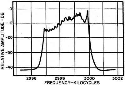
Fig. 4 - Chart showing lower sideband, suppressed carrier generation.
The carrier is at 3000 kc., the lower sideband of a 1000 cps tone is at 2999 kc.
with the 1% audio distortion second harmonic appearing at 2998. The residual upper
sideband appears at 3001 kc. at a level of -45 decibels.

Fig. 5 - Chart showing envelope of a single sideband signal transmitting
a sustained vowel sound. The suppressed carrier is at 3000 kc., the lower sideband
extends lower in frequency to approximately 2997 kc. Note that the maximum energy
of a male voice is in the lower audio frequencies which are nearest the carrier.
See text.
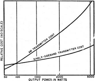
Fig. 6 - Plot of estimated cost of AM and SSB transmitters versus
the output power. (AM carrier=peak envelope power of SSB.)
Receiving SSB signals is not as simple as receiving AM signals. Since the single-sideband
signal no longer has a carrier against which the sideband signals can be heterodyned
in the receiver, the receiving station has the problem of furnishing an artificial
carrier. The most rigid requirement that the artificial carrier must meet is that
of frequency stability. The artificial carrier, whether furnished by the beat-frequency
oscillator or some other detection system to be considered later, must be within
very close frequency limits of the original transmitted suppressed carrier. Many
commercial single-sideband transmitters transmit a residual (not totally suppressed)
carrier signal so the detection of the proper carrier re-insertion frequency may
be accomplished or so that automatic frequency control equipment may be used. If
the artificially furnished carrier in the receiving system is within approximately
50 cps of the transmitted carrier frequency, the voice frequencies received will
retain all of the natural sound and, in most cases, will be recognizable as that
of the transmitting operator. For frequency deviations greater than 50 cps, an error
in the frequency relationship of the audio frequencies in the demodulated signal
will be present. The farther away the artificial carrier is from the transmitted
sideband signal the higher the voice of the transmitting operator will seem. If
the carrier is too close to the sideband signal the recovered audio speech will
appear to be very guttural and muffled and, in some cases, completely unintelligible.
Thus the first stringent limit is placed upon the single-sideband equipment to be
considered. A tuning tolerance of ±50 cycles must not be exceeded. If this tolerance
is divided evenly between transmitting and receiving facilities it means that the
transmitter and receiver must not drift from their assigned frequencies by more
than ±25 cycles.
This imposes strict limitations on any single-sideband equipment if manual tuning
is prohibited at the receiving equipment. Translated into more usual terms, a 25
cycle frequency tolerance is considerably more stringent than the 0.01% frequency
tolerance permitted under present FCC regulations. The current FCC tolerance limit
represents one part in 10 frequency deviation, while the 25 cps deviation for a
single-sideband system represents a frequency tolerance at 10 mc., for example,
of 2.5 parts in 106. This is almost two orders of magnitude greater.
This might at first appear to be unattainable with present-day equipment; however,
crystal oscillators, when used with ovens, can provide frequency stability of one
part in 106. As can be seen with a fixed frequency tolerance of ±25 cycles,
the higher the frequency of operation the more rigid becomes the percentage deviation
that must be met. Twenty-five cycles deviation at 2.5 mc., therefore, is equivalent
to a deviation of one part in 105 frequency stability.
System Gains
If we again consider the power distribution of sideband and carrier of Figs.
2 and 3 versus that of Figs. 4 and 5 for the single-sideband case it can be seen
that considerable economy of power can be effected by first eliminating the carrier
from the transmitted signal and then by eliminating one sideband. The power capabilities
can then be used to transmit a higher powered sideband signal in a decreased portion
of the spectrum. This amounts to nothing more than literally "putting all our eggs
in one basket."
The exact decibel advantage a single-sideband system has over a comparable AM
system has been discussed and evaluated in many different ways. It can be stated,
however, that the advantage of single-sideband over AM will vary with operating
conditions, that is, with signal-to-noise ratio. When the AM and single-sideband
signals being compared are well above interference and local noise levels the advantage
of single-sideband over AM will generally be in the neighborhood of 3 db. As conditions
become progressively worse, however, the advantage of single-sideband over its AM
counterpart becomes increasingly great. Some experimenters report that in extreme
circumstances where the signal-to-noise ratio is very poor, system gains of up to
16 db have been observed under actual operating conditions. A generally accepted
figure for normal operating conditions with a moderate signal-to-noise ratio is
between 6 and 9 db improvement over an equivalent AM transmitter. This discussion,
of course, assumes that narrow band single-sideband receivers are used at the receiving
locations.
If the maximum benefits of a single-sideband system are to be derived, the receivers
used in this system must have a bandwidth equal to that of the transmitted signal.
If a 3 kc. audio spectrum is transmitted at the single-sideband transmitter, the
single-sideband receiver must be capable of receiving a 3 kc. bandwidth to the exclusion
of all other frequencies. This means that some sort of intermediate frequency filtering
must be used to produce a selectivity characteristic which will sharply discriminate
against adjacent channel interfering signals and successfully pass all of the side-band
components that the desired signal is transmitting.
Economic Considerations
One of the important points to a prospective user of single-sideband would be
the initial cost of such a system and whether or not it would be possible to salvage
any of the existing AM equipment. First let's consider the installation of completely
new single-sideband equipment versus the cost of currently obtainable AM equipment.
Fig. 6 shows an estimated relationship between the cost of new single-sideband equipment
and new AM equipment of current design for various output powers between 50 watts
and 5 kilowatts. The power comparison between the two systems is such that the carrier
power of the AM transmitter is equal to the peak envelope power output of the single-sideband
transmitter. This appears to be a fair comparison and the only logical one that
can be made in view of power measurement methods with single-sideband signals. As
can be seen in Fig. 6, for transmitters with less than 100 watts output the initial
cost of a single-sideband transmitter is greater than its AM counterpart. At the
1-kw. level it is estimated that the cost of a single-sideband transmitter would
be approximately twice that of the 50-watt AM transmitter. At the 100-watt level,
however, the cost would just about equal that of the AM transmitter. At the 1-kw.
level the best estimates indicate that the AM transmitter would cost almost twice
as much as a single-sideband transmitter. As the power rating increases the difference
in AM and SSB equipment costs becomes greater. This curve can best be explained
by the fact that a certain minimum amount of equipment is necessary to generate
a single-sideband signal irrespective of power output. Any increase in power is
merely a function of the output stage and its associated power supply equipment.
However, in the conventional AM transmitter in order to increase power not only
the output amplifier stages and power supply must be increased in size, but the
high level modulating equipment must also be increased in power capabilities which
requires a larger power supply as well.
Many commercial users are going to be concerned with conversion of their present
AM equipment to single-sideband operation. In many cases this will be possible and
economically feasible. The actual conversion techniques will be covered later in
this series. If a few minimum circuit requirements are met by the existing AM equipment
it is possible to convert such transmitters to single-sideband transmission. This
would allow the user to recoup up to 75% of his capital investment in AM equipment.
In the case of low-powered AM transmitters (100 watts or less) it is believed that
many such transmitters could not be converted to SSB economically.
In such cases it would be more economical to scrap the present AM equipment and
install completely new single-sideband equipment. With transmitters having power
outputs of a few hundred watts to several kilowatts, the possibilities of conversion
to single-sideband should be carefully investigated. There are a number of different
ways of converting existing AM equipment to SSB operation. The simplest method of
conversion would be to eliminate the high-level modulation equipment of the AM transmitter
but retain the present frequency control and frequency multiplication equipment
plus the r.f. power amplifiers and power supply equipment. For many classes of commercial
service this conversion would be very successful and would undoubtedly meet minimum
FCC specifications. Let it be said, at this point, that the majority of AM transmitters
in use can be successfully converted to single-sideband operation. More on the requirements
and actual conversion later.
Single-Sideband Signal
There are two systems for generating a single-sideband signal; the older and
"classical" technique is the filter method. In this system, often referred to as
the "brute-force" system, the undesired sideband is actually filtered out or a generated
double-sideband signal.
The other system for generating a single-sideband signal is commonly referred
to as the "phasing" or "phase-shift" method of generation. This method of generation
is possible because of the recent development of wide-band audio phase-shift networks.
For a detailed explanation of the theory behind both the filter and phasing methods
of SSB generation, it is suggested that the reader refer to this author's booklet.3
Which System Is Cheaper?
Experience has shown that for signals having the same degree of sideband attenuation
the phasing and filter systems cost approximately the same in the final analysis.
As strange as it may seem, it turns out that the money that would be spent for filters
in the filter generation system is almost equaled by the money spent on the precision
components necessary in the wide-band phase-shift networks for the phasing systems.
The yet-to-be-considered linear amplifiers for the two transmitters are in every
respect identical and therefore no price differential exists. Experience has also
shown that, in many cases, there is little choice between the two systems. By this
is meant that a well adjusted and constructed phasing type transmitter will yield
the same sideband suppression as a well-constructed and adjusted filter single-sideband
transmitter.
References
1. Schlaak, N. F.: "Single-Sideband System for Overseas Telephony," Electronics,
November 1952.
2. Wrathall, E. T., & Beanland, C. P.: "The Single-Sideband System of High
Frequency Radio Transmission," Marconi Review, First Quarter, 1951.
3. Brown, J. N.: "Single-Sideband Techniques," Cowan Publishing Corp., New York.
(To be continued)
Posted July 24, 2019
|