|
December 1952 QST
 Table of Contents Table of Contents
Wax nostalgic about and learn from the history of early electronics. See articles
from
QST, published December 1915 - present (visit ARRL
for info). All copyrights hereby acknowledged.
|
Here's a topic - power supply filter
design - that never goes out of
style. It was originally published in a 1952 issue of QST magazine. Without
bothering to worry about source and load impedances, this brief tutorial on the
fundamentals of power supply filter design using series inductors and parallel capacitor
combinations. Author Gabriel Rumble offers a rule-of-thumb type formula for guessing
at a good inductor value based on peak-to-average expected current. This is by no
means a comprehensive primer on power supply filter design and is directed more
toward someone new to the concept of removing or reducing noise and AC ripple
from the output of a DC power supply.
PowerSupply Filters - Fundamental Facts for the Beginner
By Gabriel P. Rumble, EX-W5BBB
If the requirement is pure (that is, unvarying) direct current, the rectifier
outputs shown in a previous article1 will not fill the bill.
We must use the properties of L and C (or sometimes R and C) to iron out the
ripples in the rectified current.
If a condenser is placed in parallel with the load on a half-wave rectifier,
as shown in Fig. 1A, the voltage between alternations does not drop to zero,
because the condenser charges during the conducting half-cycle and discharges through
the load during the nonconducting half of the cycle, as shown in Fig. 1B.
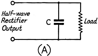
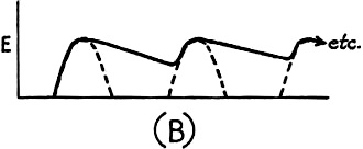
Fig. 1 - The discharge of a condenser connected across the
load resistance helps to smooth out the bumps in the output of the rectifier.
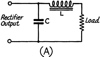
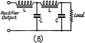
Fig. 2 - A choke in series with the load provides further
smoothing. If additional filtering is required, a second filter section may be added.

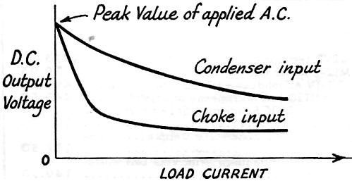
Fig. 3 - Comparison of the voltage regulation with condenser-
and choke-input filters.
A comparison of the output waveforms shown previously should make it clear why
the output of a full-wave rectifier is easier to filter than that of a half-wave
rectifier. In either case, the condenser will by-pass some of the ripple around
the load. The greater the capacitance, the slower the RC decay and the shallower
the ripple.
The action of a condenser in a filter circuit is analogous to that of shock-absorber
springs in a wagon traveling over a cobblestone road. We can further smooth out
the ride by adding weight to the wagon. This step is comparable to the addition
of a choke (inductance) to the filter circuit, as shown in Fig. 2A. The elasticity
of the condenser and the inertia of the inductor are being utilized to smooth out
the ripples that would otherwise exists across the load. Further filtering and the
consequent approach to pure direct current may be accomplished by additional sections
of filter, as shown in Fig. 2B. (Suggestion: Consult your favorite textbook
on the interesting subjects of resonant filters and swinging chokes.)
If the full rectifier output voltage is applied to the condenser, as shown in
Fig. 2A, the filter is said to be of the condenser-input type. If, instead,
the ripple voltage first undergoes an IXL drop before being applied to
the condenser, as illustrated in Fig. 2B, the filter has choke input. (Suggestion:
Look up the subject of critical inductance.)
A comparison of the voltage regulation of supplies having condenser and choke
input is shown in Fig. 3 (p. 130). With condenser input, the output voltage
varies considerably with varying loads. With choke input, the output is almost constant
for a wide range of load variation. The variation occurring in this flat range is
caused by the d.c. resistance of the choke and rectifier resistances and the leakage
reactance of the transformer. However, in well-designed components these are usually
quite low. The load current at which the knee of the curve occurs is dependent on
the inductance of the input choke. The greater the inductance, the smaller the value
of load current at which the curve starts to flatten out.
In addition to providing a flatter characteristic, the use of choke input has
another advantage. It reduces the ratio of peak to average current passed by the
rectifier. If it were desired to design a rectifier for a fixed load current of
I amperes and E volts, and if it were further desired that the peak rectifier current
should exceed the average by only P%, then the inductance, L, in henrys, of the
input choke, should be
L = E / (10*P*I), where:
L is inductance in Henries
E is peak voltage
I is peak current
P is peak-to-average current ratio
The knee of the characteristic will occur at a current of P*I amperes. If it
were desired to have the knee at a lower current, a smaller value of P would be
selected and a higher L would be called for. Where good regulation down to low values
of load current is not of interest, and the values of full-load current and rectifier
current rating permit, the values of P above 5 per cent will usually be more economical.
Filter chokes are usually placed in the ungrounded side of the rectifier output.
If the choke is placed in series with the transformer and ground, the capacitance
of the secondary winding of the transformer to grounds tends to by-pass the choke.
If the expected current drain on a rectifier is very slight, resistors, which
are comparatively inexpensive, may be used in place of the chokes. A 1000-ohm resistor,
for example, will do just as much filtering as 1000 ohms of inductive reactance
at any given ripple frequency. It should be stressed that this is practical only
when the load resistance is much higher than the filtering resistance. Also, the
d.c. voltage drop in the filter resistor and its adverse effect on regulation must
be taken into account.
1 Rumble, "How Rectifiers Work," QST, October, 1952, p.42.
Posted June 30, 2022
(updated from original post on
4/14/2016)
|