|
February 1939 Popular Science
 [Table of Contents] [Table of Contents]
Wax nostalgic about and learn from the history of early
electronics. See articles from
Popular
Science, published 1872-2021. All copyrights hereby acknowledged.
|
Few things give away the
era of an electronics article than having capacitor values presented in units of
micromicrofarads (mmf.) rather than picofarads (pF). The change is not merely the
use of micromicro (10-6 x 10-6 = 10-12), but also
the use of lower case "m" to designate micro (as opposed to milli). Periods are
no longer placed after the abbreviation. The lower case
Greek letter "μ"
was adopted for use in 1960 by the National Bureau of Standards (NBS, now NTIA)
and the International Committee on Weights and Measures. Four new prefixes were
proclaimed tera, meaning trillion (1012); giga (109), meaning
billion; nano, billionth (10-9), and pico, trillionth (10-12).
Finally, "farad" nowadays is printed as an upper case "F." Not many people are
in the market for replacement electronic parts since most components require
special soldering equipment to remove and mount. Components in 1948, when this
article appeared in Popular Science magazine were fairly easily
serviced.
How to Buy Radio Parts

Knowing what to buy and why is the first step to successful shopping,
and the key to building electronic gadgets that work.
By Frank Tobin
Should you ask a radio-parts salesman for a "double-o-one-mike condenser," he
could put out a counterful of parts - all different, yet all 0.001-mfd. capacitors.
"Which do you want?" he might ask. "Paper, mica, or ceramic - and what voltage and
tolerance?"
If your first impulse is to say that it makes no difference so long as the capacity
is right, you've probably never seen the wax melt out of a paper condenser used
where a mica should have been. Sometimes, to be sure, identically rated parts may
be used interchangeably. But don't overlook the many cases where an improper part
may cause a short, burnout, or open circuit, or simply become defective in a hurry.
Some of the things that are worth knowing about condensers, coils, resistors,
output transformers, and tubes are dealt with in this article. You may find them
helpful next time you shop for radio parts.
Condensers - Fixed and Variable
Mica condensers (Fig. 1) are easily recognized by their molded-plastic cases.
They are commonly used in by-pass and coupling circuits and as grid condensers in
grid-leak detectors. Their working-voltage rating is generally about 500 volts DC
but the cases are rarely marked. Mica condensers are used mostly at high frequencies,
and therefore capacities are low, ranging from about 50 mmf. to 6,000 mmf. (0.006
mfd.). You'll find micas in demand wherever low capacities with low loss at high
frequencies are required.
Incidentally, in case condenser arithmetic has you stumped, the basic unit of
capacity is the farad. As radio components go, this unit is enormous, so it's divided
by a million. This gives the microfarad (mfd.) and can be expressed as 0.000001
farad, (one millionth farad) but would normally be written 1 mfd. Even that's big
in radio work, so the microfarad is further divided by a million to give the micromicrofarad
(mmf.) which can be written 0.000001 mfd. or, more simply, 1 mmf. To translate mfd.
to mmf., simply move the decimal six places to the right (in effect, multiply by
a million). Thus 0.0001 mfd. is the same as 100 mmf., and 0.005 mfd. becomes 5000
mmf.

Fig. 1 - Common capacitor package styles.
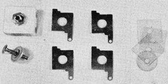
Fig. 2 - Mica and metal plates for making custom condensers.

Fig. 3 - Variable tuning capacitor (condenser).
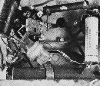
Fig. 4 - Unshielded oscillator core.

Fig. 5 - Cut-away view of inductor.
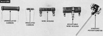
Fig. 6 - Fixed and variable resistor styles.

Fig. 7 - Inside view of panel-mounted switch.
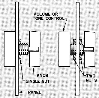
Fig. 8 - Methods for mounting switches and potentiometers to
panel.

Fig. 9 - Vacuum tube package styles.
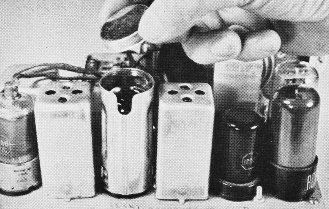
Fig. 10 - Various styles of metal tube and inductor shields.
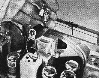
Fig. 11 - Indicator bulbs (incandescent and neon).
One of the war-developed ceramic capacitors will often do when specifications
call for mica. Ceramics have high stability and compactness; they come in the form
of small disks or tiny cylinders resembling fixed resistors (Fig. 1). They are also
primarily for use in radio-frequency (RF) circuits.
Paper condensers can be found in every stage of a modern receiver. They have
such varied functions as bypassing stray signal voltages, coupling two stages, bass
boosting (in tone-control circuits), and filtering in certain rectifier applications.
Working voltages are usually indicated for paper condensers; and it is important
that the rating be adequate. When in doubt always take a larger voltage. In AC-DC
or battery-operated receivers a condenser rated at 400 volts allows a safe margin.
You might get by with these even in an AC set or amplifier that delivers 250 to
350 volts of B plus, but a few pennies more can buy greater safety in the form of
600-volt condensers. Sometimes heat generated by tubes may melt the wax in which
a condenser is sealed. Where this seems likely, try to get capacitors sealed in
plastic.
There is still another type of fixed condenser that crops up in practically every
piece of radio or electronic equipment - the electrolytic. This is used in all filter
circuits and in many special applications. Electrolytic condensers come in aluminum
cans or cardboard containers. In order to save space (and cost), two or more units
are often put in one container with separate leads brought out. A single can containing
two units is called a dual electrolytic; multiple electrolytics with up to four
sections are common. Polarity must be observed for electrolytics, so make sure the
leads are color-coded or otherwise marked. Standard codes use red for the positive
and black for the negative terminals.
Fixed condensers sometimes vary from rated value by as much as 20 percent plus
or minus. Except for test equipment or the like you can usually allow an extra margin
of up to 20 percent when you can't find a condenser of the right size. If the parts
list calls for 0.005 mfd., you can get by with 0.006 or 0.004 mfd. But for very
exacting equipment it is frequently wise to pay more for condensers guaranteed within
5 percent of stated capacity.
The variable condensers used for tuning shortwave or broadcast receivers are
usually 0.00014 mfd. (140 mmf.) or 0.000365 mfd. (365 mmf.). They're available either
as single units or ganged into two or three sections. The type to buy depends on
the number of tuned circuits in the set. Ganging of two condensers of unequal size
is common in superhets to tune the antenna and the oscillator circuits to different
frequencies.
Experimenters almost always find it wise to purchase variable condensers with
built-in trimmers. These are sandwiches of metal and mica (Fig. 2). A setscrew squeezes
the metal plates more tightly when you have to increase capacity, or relieves the
pressure to reduce capacity. Fig. 3 shows trimmers mounted directly above the variable
plates.
Trimmers are built into most IF transformers to enable you to make minor adjustments.
They also come separately for use in coupling an antenna to an antenna coil, as
padders in oscillator circuits, and even as tuning condensers in midget receivers.
Coils
Coils constitute another large and often bewildering category to the man who
sets out to buy radio parts. Under this head you will find plug-in, antenna, RF,
oscillator, and IF transformer coils. Some are shielded, some aren't.
Plug-in coils, found in simple crystal and regenerative receivers, are generally
sold in matched sets to cover broadcast and shortwave bands. In most cases the tuning
condenser is of 140-mmf. capacity. Four-prong coils are used when the circuit calls
for two windings, while six-prong coils are needed for three windings.
Antenna and RF coils are employed in small TRF receivers. They are available
either shielded or unshielded. When using unshielded coils, it is best to mount
the antenna coil above the chassis and the RF coil underneath so the chassis will
serve as a shield. Wherever it is necessary to mount all coils on one side of the
chassis, or where there's more than one tuned RF stage, only shielded units should
be used. In buying receiver coils, ask for a matched set. This will assure accurate
ganging between coils as well as with the condensers.
Most superheterodyne circuits call for an antenna coil, and they always require
an oscillator coil, and at least two intermediate-frequency (IF) transformers. Shielding
problems are the same as in the TRF set. In the lower foreground of Fig. 4 an unshielded
oscillator coil is mounted underneath the chassis.
The transformers used to couple IF stages are basically coils tuned to a fixed
frequency - in broadcast receivers 456 kc. They are in aluminum cans (Fig. 5 shows
one cut away) with lugs, clips, or feet by which they can be mounted.
Some IF transformers are brought to peak frequency by trimmers, and some by adjusting
an iron core. The latter respond over a much broader tuning range and are therefore
easier to align without a signal generator.
One final point to bear in mind when buying coils: If you are building a receiver
with only a single stage of RF or IF, you need maximum amplification in each stage.
You will get this plus greater selectivity by using coils with iron cores.
Fixed and Variable Resistors
You'd have to look hard for an electronic circuit that doesn't use a fixed or
variable resistor of some kind. Fixed carbon resistors constitute the bulk of all
resistance units. They are inexpensive, reasonably accurate, and come in a large
variety of sizes and ratings. Some are encased in plastic, which makes them impervious
to moisture and less likely to short against other components. Uninsulated resistors
(Fig. 6) dissipate heat a little more readily but shouldn't be used in cramped quarters.
All fixed resistors are rated in ohms (the unit of resistance) and watts (current
rating). As with voltage ratings in condensers, a larger wattage is safer when there's
doubt.
For AC-DC receivers and amplifiers, 1/2-watt units are generally adequate in
the control-grid circuits of amplifier tubes. Plate and screen circuits should get
1-watt resistors, and cathode and filter circuits 2 watts or more. Battery-operated
equipment can generally get by with ratings half as large.
Wire-wound resistors are employed where current drain is high and where stability
and accuracy are paramount. On adjustable wire-wound resistors part of the winding
is left bare so that a movable metal band can tap off any resistance between zero
and the maximum.
Variable resistors, now found chiefly in the form of potentiometers, have a fixed
carbon or wire-wound element and a moving contact turned by a shaft. If you want
resistance to increase evenly in proportion to shaft movement, specify a linear-taper
pot. Because of tube characteristics, nonlinear pots usually give more gradual control
over volume, tone, and bias. In logarithmic pots, usually used for tone and volume
controls, resistance increases at a definite but uneven rate. In end-tapered pots,
used for varying tube bias, resistance "thins out" at one end.
For the convenience of radio builders, the makers of potentiometers provide switches
that can be slipped onto the back of the unit (Fig. 7). The switch is actuated by
the first few degrees of shaft turn.
A potentiometer is usually fastened to a panel by means of a gripping nut screwed
on a threaded shaft. Since there is a good deal of variation in shaft nuts, you
can often do yourself a favor by purchasing an extra one at the time you buy the
potentiometer. With two nuts you can exactly regulate the projection of the shaft
in front of the panel as shown in Fig. 8.
Output Transformers
In purchasing an output transformer for a small set, it is best to look for the
universal type. Taps on the secondary winding of the transformer (Fig. 9) allow
matching of any tube impedance from 1,500 to 20,000 ohms to any voice-coil impedance
from 0.1 to 24 ohms. These figures vary somewhat with different makes.
Impedance matching is probably the leading consideration in the selection of
an output transformer, but there is one other that must never be overlooked. If
the transformer can't handle all the plate current that will be delivered to it,
it cannot transfer that power to the speaker. Output transformers are rated in watts.
For most battery and small AC-DC receivers, 4 to 5 watts is suitable; for AC receivers
and high-powered audio amplifiers you will usually want a transformer rated at 8
watts or more.
Tubes and Pilot Lights
Some people feel that radio tubes offer the largest variety of radio components.
Several catalogs list upward of 400 types. This, however, need rarely worry the
builder who works from a parts list. The specifications always designate tubes by
numbers.
One puzzling element is the lettering that follows the tube number. A metal 6K7,
for example, has the same electrical characteristics as the glass-dome 6K7-G or
the bantam 6K7-GT (the latter is sometimes listed as GT/G). The only differences
are in their physical dimensions (Fig. 10) and in the method of shielding. The first
of these tubes is encased in metal, the other two in glass envelopes of different
sizes (G being considerably larger than the GT). The 6K7 requires no separate shielding,
while the others must be covered with a metal shield (Fig. 11) to suppress undesirable
coupling. Only tubes used in the high-frequency circuits - RF, converter, IF, and
sometimes detector stages - need shielding; others such as power output tubes and
rectifiers don't require it. Fig. 10 shows the most common types of receiving tubes,
being, from left to right, sub-miniature, miniature, bantam (GT), metal, and glass
dome (G).
Sometimes you want to duplicate a particular circuit in a smaller size. This
is becoming increasingly possible with miniature components. For example, the 50L6
beam-power amplifier can be replaced with a 50B5 miniature.
Dial pilot bulbs become critical in AC-DC sets, because they're in series with
the tubes and must match them in current rating, since current is equal in all parts
of a series circuit. The bulb ratings are marked by a colored glass bead in the
bulb. For example, a set using tubes with heaters drawing 0.15 amp at 6.3 volts
calls for a brown-bead pilot bulb. A white bead means 0.5 amp. at 2.5 volts, a blue
0.3 amp. at 6 to 8 volts, and a pink one 0.06 amp. at 2 volts. All types come with
both bayonet and screw bases to suit the two socket types (Fig. 12).
Posted February 9, 2024
|