|
September 1949 Popular Science
 [Table of Contents] [Table of Contents]
Wax nostalgic about and learn from the history of early
electronics. See articles from
Popular
Science, published 1872-2021. All copyrights hereby acknowledged.
|
When writing an article
about radio beams measuring an airplane's passage through the skies, using the phrase
"crashes through the beam" is not a particularly good choice. This particular system
from a 1940 issue of Popular Science magazine reports on a system being
used by the U.S. Air Force to accurately measure airspeed over an 11−mile course.
It claims timing is accurate to 1/1,000 of a second (1 millisecond), while flying
as high as 30,000 feet. An example is given where a jet fighter made the 11.0533−mile
run in one direction in 74.25 seconds, which calculated to approximately 535 m.p.h.
(my calculator gets 536 mph). For an accuracy of ±1 ms, that means the
speed could range between 11.0533/73.25*3600 = 529 mph and 11.0533/73.25*3600
= 543 mph. At the 536 mph rate, in 1 ms the airplane travelled 0.786
feet (9.43 inches).
Radio Beams Flag Planes
Fastest planes docked by electronic equipment that can tick off
flying lime between exactly spaced radio "walls."
By Herbert Johansen
Drawings by Ray Pioch
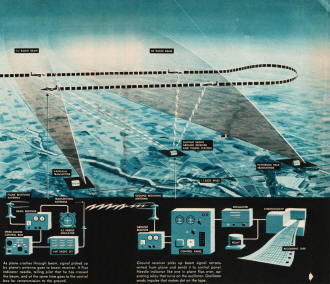
Left: As plane crashes through beam, signal picked up by plane's antenna goes
to beam receiver. It flips indicator needle, telling pilot that he has crossed the
beam, and at the same time goes to the control box for retransmission to the ground.
Ground receiver picks up beam signal retransmitted from plane and sends it to
control panel. Needle indicator like one in plane flips over, operating relay that
turns on the oscillator. Oscillator sends impulse that makes dot on tape.
Streaking between two parallel radio beams that flare into space 11 miles apart,
Air Force speedsters can now be timed automatically with an accuracy of 1/1,000
of a second. "And they can fly as high as 30,000 feet while making their speed runs.
The ballistic cameras previously used for timing (PS, Sept. '47, p. 150) forced
planes to make their passes at extremely low altitudes if they were to keep in the
picture. Now, with the new all-altitude speed course developed by the Air Materiel
Command at Wright-Patterson Air Force Base, Dayton, O., not only is accuracy increased,
but the sky's the limit.
The two vertical radio beams - which act like electronic versions of the start
and finish flags used in auto races - are provided by very-high-frequency transmitters
on the ground. One is located at Patterson Field and the other at Vandalia, exactly
11.0533 miles apart. The trick is to make these beams like sheets, or walls - very
wide vertically yet very narrow (about two degrees) horizontally. This is just the
opposite of ordinary broadcasting, in which radio waves are scattered all around
horizontally.
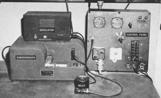
Telemetered signal from plane is interpreted on the ground and
recorded by equipment above.
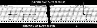
Sample of tape shows how start and finish beam-crossings are
recorded on tape running through the chronograph. Since elapsed time between beams
was 74.25 seconds, and distance is known to be 11.0533 miles, ground speed of plane
in this test run was approximately 535 m.p.h.
At Sulphur Grove, about halfway between, is a third station. It houses receiving
equipment and a chronograph unit that records the actual timing on a moving tape.
It also has a transmitter to send out a third beam, providing a shorter course for
slower aircraft and a check point for the entire course.
The aircraft also carries special radio receiving and transmitting equipment.
The instant the plane passes through a beam, this equipment signals the ground receiving
station. The signal triggers the chronograph.
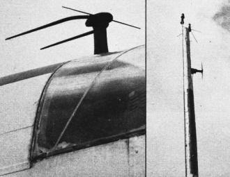
Beam-receiver antenna on plane is shown at left below. At right
is close-up of antenna pole at Sulphur Grove. Antenna for transmitter is on top,
and that for receiver and timer below.
In making a speed run, the pilot calls the ground timing station on voice radio
to announce that he is approaching the first beam. The tape is started running through
the chronograph. As he "crashes" through the beam, the beam signal picked up by
his receiver flips the needle on an Instrument-Landing-System indicator, telling
him that he has crossed the first beam. He then switches to the channel frequency
of the second beam. At the same time, the beam signal he has received is automatically
retransmitted to the central ground station.
Picked up by the ground receiver, the re-transmitted signal causes an oscillator
to feed an impulse into the chronograph, marking on the tape the exact instant the
beam was crossed. The tape continues to run until the plane crosses the second beam,
when a similar chain of events occurs.
While the marked portion of the tape is removed and labeled, the ground personnel
stand by for the pilot to announce that he is ready to make a second run. Two passes
are made, one in each direction, to compensate for wind velocities.
Posted February 14, 2024
|