|
May 1946 Popular Science
 [Table of Contents] [Table of Contents]
Wax nostalgic about and learn from the history of early
electronics. See articles from
Popular
Science, published 1872-2021. All copyrights hereby acknowledged.
|
Some of the earliest printed
circuit boards were literally printed onto a ceramic substrate using silk−screening
techniques. For that matter, silk cloth was used as the pattern mask; hence the
name silk−screen. A paste of silver particles was squeegeed through the mesh, and
the resulting circuit pattern was fired in an oven to solidify and adhere the
metal to the substrate. Holes were then drilled to accept component leads. After
inserting the leads through the holes, hand-soldering completed the assembly. It
was a game-changing technology. Not only was time and space saved and a more robust
product the result, but the process eliminated miswiring and made tracing out interconnections
much simpler when troubleshooting. According to this 1946 Popular Science
magazine article, the motivation for developing this technique was the proximity
fuse during World War II. Ditto for the tiny "peanut tubes" used. Necessity
is the mother of invention, as the saying goes.
Printing Radio Sets on Calling Cards
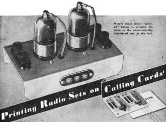
Minute radio circuit "printed" below is actually the same as
the conventionally assembled one at the left.
Tiny Circuits of Silver "Ink" Baked on Ceramic Base Plates
By Hartley E. Howe
Techniques borrowed from the graphic arts now "print" whole radio circuits. The
maze of wiring is replaced by a pattern of silver "ink" on a ceramic base as hard
as a gem. Resistors are sprayed on. Condensers are paper-thin disks. Tubes are the
size of flashlight bulbs. The result is a circuit that is not only extremely compact,
but rugged, simple to check and repair, and easy to manufacture quickly and precisely.
Once again one industry has borrowed a process from another, as in the adaptation
of paper-making techniques to tin-plate manufacture. In this case, it is the familiar
silk-screen process used in printing labels, posters, and textile designs. With
it, a master circuit can be reproduced simply and exactly from a pattern almost
as easily as a calling card is printed.
Behind the new application of this old process lies a wartime search to perfect
one of our most potent secret weapons, the proximity fuse (PSM, Dec. '45, p. 86).
This deadly gadget enabled an antiaircraft gun to knock down a hostile plane without
a direct hit, by an elaborate electrical hookup that exploded the shell as it neared
the target. The fuse, no longer than an ordinary radio tube, carried a completely
self-contained turbogenerator, control circuits, safety devices, and an entire radio
transmitter-receiver.
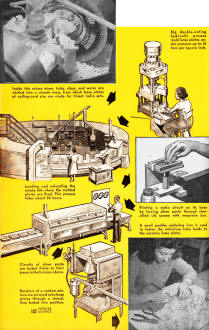
Inside this rotary mixer, talcs, clays, and water are whirled
into a smooth mass, from which base plates of calling-card size are mode for tiniest
radio sets.
Big double-acting ,hydraulic presses mold base plates under pressure
up to 10 tons per square inch.
Loading and unloading the rotary kiln where the molded plates
are fired. This process tokes about 24 hours.
Printing a radio circuit on its base by forcing silver paste
through stenciled silk screen with neoprene bar.
Circuits of silver paste are baked firmly to their bases in the
furnace above.
Resistors of a carbon mixture are sprayed onto base plates through
a stencil, then baked into position.
A small penlike soldering iron is used to fasten the miniature
tube leads to the ceramic base plate.
The space problem was tough enough, but a worse one was the terrific impact that
the fuse had to sustain at the moment of firing - equal to a blow 10,000 times its
own eight. Conventional wired circuits just couldn't take it.
The whole problem was turned over to the National Bureau of Standards, working
with the Centralab Division of Globe Union, Inc. Centralab had a lead toward a solution.
Before the war its researchers had worked on a way to build capacitors and resistors
by bonding silver to ceramics. Now they applied the principle to whole circuits
- wiring, capacitors, and resistors all on one ceramic base. It worked; the proximity
fuse began smelling out and destroying enemy planes in upper space - and today's
printed circuits are available for peacetime uses.
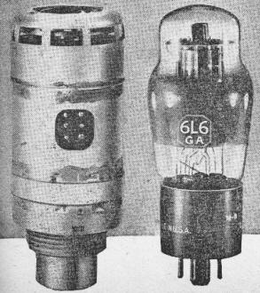
Methods developed to build an entire radio transmitter-receiver
into the deadly proximity fuse, here compared in size to a standard radio tube,
are used in printing radio circuits for commercial purposes.
First step in printing a circuit is to make a pattern, which is photographed
and printed on a silk screen coated with sensitive emulsion. The portions masked
by the pattern are water-soluble and can be washed away, leaving the exposed emulsion
on the silk in a stencil pattern of the circuit.
The "ink" is finely divided metallic silver or silver oxide mixed with binders
and solvents to form a paste. This is spread on the screen, which is placed on the
ceramic base plate. A neoprene bar is then pulled along the screen, forcing the
silver through the stencil onto the surface of the plate to print the circuit. The
silk mesh makes the deposit uniform throughout. It is fixed in place by baking it
at a temperature between 1,300 and 1,500 degrees. The heat removes the solvents
and binders and leaves the pure silver bonded to the plate with a tensile strength
of about 3,000 pounds to the square inch.
The circuit completed, the next step is to add the resistors. These are also
"ink," but a different compound: a conducting material such as finely divided carbon,
an inert filler, a binder and a solvent. By combining proper proportions of these
elements, and making variations in the dimensions of the resistor, exact resistances
can be made ranging from 3 ohms to 200 megohms.
The carbon mixture is sprayed on the base plate through a stencil, and after
air drying the plates are again baked, this time at the much lower temperature of
300 degrees. After being coated with resin the resistors are highly stable under
heavy loads or high humidity.
The capacitors or condensers are the third element to be added to the circuit.
These are also of a novel type: paper-thin ceramic disks, silvered on both sides
and from 1/8 to 3/8 of an inch in diameter. Attaching these tiny capacitors to the
base plate is a delicate job. A low-temperature bismuth solder must be used because
the heat of normal soldering would crack the thin condenser plates. In addition,
two percent silver must be added to the solder to prevent it from absorbing the
silver from the base plate.
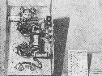
The bottom of a regular radio chassis, with its clutter of wires
and parts, contrasts strikingly with the compact base plate of a printed radio circuit,
shown at a comparable stage of assembly.
Since ordinary solder would soak up the circuit, silver solder is also used in
the final step, adding the tubes. The new tiny tubes developed during the war, highly
efficient, rugged, and with an extremely low-filament drain, are used to keep the
unit compact.
The plates on which the circuits are printed are made of a ceramic called steatite.
When molded, under great pressure, the plates are chalklike. To shrink and harden
them, they are dipped in glass-forming materials and fired in kilns at around 2,400
degrees Fahrenheit. When they come out they are hard enough to cut glass. Steatite
will not absorb water, solvents or acids even when completely submerged - extremely
important for electrical use.
Centralab does not plan to produce complete radio sets itself but rather component
parts, including amplifiers, filters, control circuits and small subassemblies,
for other manufacturers. Subcircuits printed on plates plugged into the main chassis
are as easy to change as a tube. This is particularly important in the export trade:
radio repairmen are few in remote areas and a plugged-in circuit that can be bought
as a unit, like any spare part, will enable the owner to make his own repairs.
Vest-pocket radio telephones to be carried by individuals still lie in the future
but there are many immediate uses for the tiny circuits. Hearing aids can be made
far smaller and more compact. Meteorological instruments can be lighter and stronger.
Electronic controls of all sorts, in fact, will benefit from the ruggedness and
simplicity of the silver circuits, and from the small amount of space they occupy.
Posted November 28, 2023
|