|
July 1965 Popular Electronics
 Table of Contents Table of Contents
Wax nostalgic about and learn from the history of early electronics. See articles
from
Popular Electronics,
published October 1954 - April 1985. All copyrights are hereby acknowledged.
|
I like the opening line to
this 1965 article on using silicon diodes, "You can stack' em up to get all the power
supply voltage you need, but you have to know how to dress 'em up." The basic rules
of solid state diode implementation have not changed much since they first began
gaining widespread usage. Observing peak inverse voltage (PIV), forward and leakage
current, and power dissipation rating limits were and still are the primary concerns
for diodes. Moving to higher frequencies, particularly in communications
applications, requires attention to junction capacitance, self-generated noise, and
forward and reverse recovery times. Physical size and ruggedness, temperature and
humidity, and even shielding from cosmic rays can also need careful consideration.
That's partly what the author meant by dressing them up. BTW, we are so accustomed to
using semi diodes these days that these days an article titled, "Using Vacuum Tube
Diodes" would send the type of adrenalin rush to readers that this one did in the
1960's.
Using Silicon Diodes
 By Charles L. Fair, W7ZMH By Charles L. Fair, W7ZMH
You can stack' em up to get all the power supply voltage you need, but you have to
know how to dress 'em up.
Most experimenters at one time or another probably toy with the idea of substituting
silicon diodes for the vacuum tubes in their power supplies. After all, with silicon
diodes there is less power consumption, less heat, less need for replacement, and less
space required. All too often, however, this apparent panacea to vacuum-tube ills backfires,
cancelling out the benefits and leaving you up in the air as to what went wrong.
Often occurring without an obvious reason, power supply failures are especially numerous
when several diodes are used in series to handle high voltage and resulting high peak
inverse voltage (PIV). If you are planning to convert that power supply of yours, the
following suggestions can save you time and money.

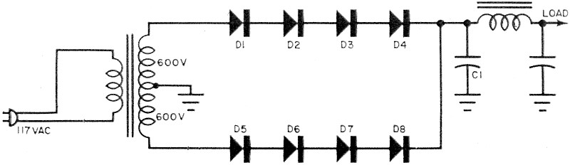
Fig. 1 - Inviting trouble: variations in diodes' reverse resistance
cause unequal distribution of power supply circuit's inverse voltage and can start a
chain reaction of destruction. Transients don't help either.

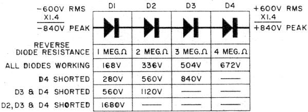
Fig. 2 - Although each diode has a PIV rating of 600 volts and they
appear to give the circuit above a total PIV capability of 2400 volts, it cannot handle
even the 1680 volts developed across the diode chain. The table shows why D3, D2, and
D1 play follow the leader in rapid order once D4 shorts out.

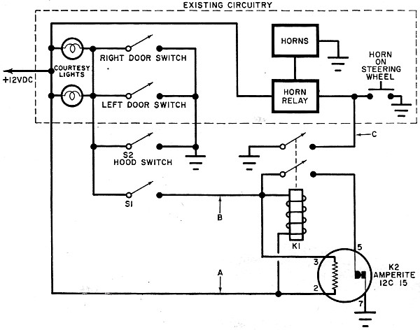
 Existing door switches for courtesy lights can be
used to trigger the alarm. Externally mounted switch S1 can be concealed or lock-and-key
protected. The normally closed delay relay, K2, holds K1 for a predetermined time to
sound the alarm, then lets go and automatically resets itself when the bimetal contact
holder, under the influence of the heater, opens and closes the contacts. Existing door switches for courtesy lights can be
used to trigger the alarm. Externally mounted switch S1 can be concealed or lock-and-key
protected. The normally closed delay relay, K2, holds K1 for a predetermined time to
sound the alarm, then lets go and automatically resets itself when the bimetal contact
holder, under the influence of the heater, opens and closes the contacts.

Wiring and component location are not critical. The finished unit
should be mounted inside the car.
Diode Characteristics. First let's briefly review some important
diode characteristics. A silicon diode conducting in the forward direction has a voltage
drop of one or two volts across it because of its small forward resistance. The same
diode exhibits a very high resistance - usually on the order of several megohms - when
a reverse voltage is applied. The actual value of this forward and reverse resistance
varies from diode to diode, even if they are the same type, unless they are a matched
pair. It's this variation in resistance, as we shall see, that is one of the prime causes
of series-connected diodes breaking down.
Figure 1 shows an unprotected silicon diode power supply using a 1200-volt center-tapped
power transformer and a capacitive-input filter. Each diode string has to rectify 600
volts 50% of the time. While this is a full-wave configuration, the same considerations
apply to half-wave circuits. The PIV across each diode string is obtained by multiplying
the 600 volts by a factor of 2.8. This works out to be 1680 volts. Good design practice
calls for an added 25% safety factor, bringing the PIV requirement to 2100 volts.
Just in case you are wondering how the 2.8 factor is arrived at, keep in mind that
the transformer voltage rating is reported out in r.m.s. volts. The same r.m.s. potential
reported out in peak volts would be a figure 1.4 times greater. Capacitor C1 charges
up to peak voltage, and retains peak voltage even while the a.c. voltage on the transformer
end of the diode string swings negative. The r.m.s. voltage across the string when the
transformer end is maximum negative (-600 volts) and the capacitor end is positive (600
volts) is 1200 volts. Multiplying 1200 volts by 1.4 to determine the amount of peak volts
is the same as multiplying 600 volts by 2.8. The result is 1680 volts.
Four 600-volt PIV silicon diodes of the type used here (1N614's) would normally boost
the overall PIV rating of the circuit to 2400 volts. However, you can consider yourself
lucky if you are able to operate at anywhere near this level without breaking down.
PIV Variations. To illustrate the harmful effects of variations in
the reverse resistance characteristic, let's assume back resistances of 1, 2, 3, and
4 megohms on D1 through D4, respectively. The voltage drop across each of these diodes
at 1680 PIV is shown in Fig. 2.
Since each diode has a maximum PIV rating of 600 volts, D4 would in time fail - because
it has 672 volts across it. In most instances a diode that fails in this manner acts
like a very low resistance and an effective short circuit. Once this happens, the voltage
distribution changes, leaving 840 volts across D3. It doesn't take long for D3 to fail;
D1 and D2, of course, would also fail, as shown in the table in Fig. 2. Just in case
D4 is stout enough not to break down when it sees the extra 72 volts, it will soon change
its mind when an additional voltage comes along, such as a transient kicked up by switching
the circuit on and off, or by sudden changes in the load circuit.
To prevent this chain reaction of destruction, shunt each diode with a resistance
of much lower value than the back resistance of the diode. The inverse voltage drop will
then be nearly independent of the diode's back resistance. A 250,000-ohm resistance across
each diode will usually do the trick. If all resistors are of equal value, the PIV across
each diode will be the same.
Transients. Transient voltage pulses are of extremely short duration
and have a high-frequency characteristic. This characteristic enables us to use capacitors
to distribute transient voltages in a harmless manner. In addition to forward and reverse
resistance, each diode has a certain amount of capacitance, and like diode resistance,
the capacitance varies from unit to unit.
Just as the variations in resistance are compensated for by shunting external resistors
across each diode, you can shunt each diode with a capacitor. The capacitive reactance
of the external mounted on the firewall or under the dash by drilling two holes in the
bottom of the other half of the chassis and fastening it with self-tapping screws in
any convenient location.
In order to save a lot of time and trouble installing special alarm switches on each
door, you can use the existing courtesy light switches. The lead from the master alarm
switch (S1) must be tapped into the grounded side of either courtesy or dome light lead
between the light and the switch. This switch must be located on the car's exterior.
A simple toggle switch can be used if it is concealed in the grille, behind the bumper,
etc., or an ignition lock type switch might be used. The author used a toggle switch
and mounted it in the recessed area near the rear license plate on his Corvair.
A new switch, S2, must be mounted under the hood in such a position that when the
hood is down the switch is open. One terminal is grounded and the other is connected
at the same point as the lead from S1.
Other Uses. The basic circuit of this alarm can be adapted for many
different applications. By selecting the proper relay and delay relay values, a home
alarm system can be built, using a floodlight, siren, etc., as the actual alarm. This
system can also be used in a boat, or as a control for any other type of alarm.
Posted May 10, 2018
|