|
August 1965 Popular Electronics
 Table of Contents Table of Contents
Wax nostalgic about and learn from the history of early electronics. See articles
from
Popular Electronics,
published October 1954 - April 1985. All copyrights are hereby acknowledged.
|
Restoring and/or upgrading
vintage radio receivers is still a very popular pastime for hobbyists, and for that
matter for some professional servicemen who preform maintenance on established equipment
installations. Three of the most significant changes that can be made to older receivers
to improve sensitivity are to clean up the power supply DC output, replace noisy
components like vacuum tubes and leaky capacitors, and tune / modify / replace RF
and IF filters. This 1965 Popular Electronics magazine article discusses
a method of replacing a stock LC filter with a high selectivity mechanical filter.
The nice thing about an analog receiver is that narrowband, steep-skirt filters
can be substituted without concern for group delay at the band edges that can (and
will) wreak havoc on digital signals.
Super Selectivity for Your Receiver
Mechanical filter sharpens bandwidth for
optimum reception of AM, CW, and SSB.
By Charles Caringella W6NJV
If your receiver or transceiver employs a 455-kc. Lf. strip, sharp selectivity
can be achieved by substituting a recently introduced mechanical filter (Lafayette
99 K 0123) for the first i.f. transformer to help you cope with today's crowded
radio bands. Several important advantages make this installation highly desirable.
Steep skirt selectivity makes it possible to overcome the masking effects of
strong or local signals as little as 5 kc. away. Once the filter is installed, it
doesn't need to be adjusted while the receiver is in operation. No objectionable
effects such as ringing or hollow sounds commonly associated with crystal filters
are present. The filter can be installed in most vacuum-tube-type amateur, commercial,
or CB equipment. Finally, it works well in AM, CW, and SSB receivers.
How It Works
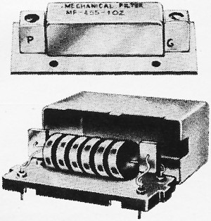
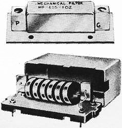
The mechanical filter is basically an electromechanical
device. It consists of an input transducer, a resonant mechanical section having
several metal discs, and an output transducers, as shown above. Both transducers
are crystal types. An electrical signal applied to the input transducer is converted
into mechanical vibrations which travel through the resonant mechanical section
to the output transducer, where they are reconverted to electrical signals.
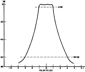
Fig. 1 - Bandwidth of 2 kc. at 6 db expands slowly to 6
kc. at 60 db. Steep skirt characteristic makes it possible to separate closely spaced
stations.
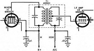
Fig. 2 - Typical receiver first i.f. stage before modification.
Internal circuitry of transformer can be ignored. However, the frequency of the
mechanical filter should be the same as the transformer to be replaced.
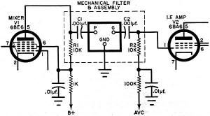
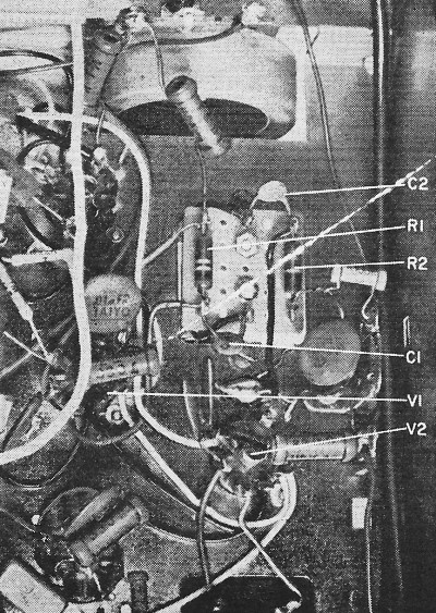
Fig. 3 - In addition to the mechanical filter, only two
capacitors and two resistors are added (within the dotted lines). Once the filter
is installed and the remaining i.f. transformers have been peaked, no further adjustments
need be made.
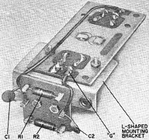
Fig. 4 - Mechanical filter and added components are grouped
together into a subassembly and mounted in the same manner as the original i.f.
transformer.
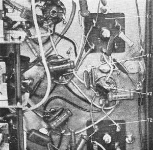
Fig. 5 - Bottom view of receiver before the first i.f. transformer
(T1 ) is removed. It is not necessary to disturb any other part of the receiver.
The selectivity characteristics of the filter are determined by the resonant
metal discs. Each disc is carefully machined to extremely close tolerances to make
it vibrate at a desired frequency, such as 455 kc. The discs are made of a ferro-nickel
chromium alloy for extreme hardness and resistance to corrosion. Each is supported
by - and coupled to the others with - a thin rod. The rod runs the entire length
of the filter, and is attached to the transducer at each end. Only those signals
within the filter's passband can get through.
Nominal bandpass characteristics of the filter used in this project are shown
in Fig. 1. At 6 db down on the response curve, the bandwidth is approximately
2 kc.; and at 60 db down, the bandwidth is approximately 6 kc.
It is natural for mechanically resonant elements, such as metal discs, to have
multiple resonances which allow spurious transmissions through the filter at frequencies
other than those in the primary passband. By employing conventional type i.f. transformers
at the input and output ends of the filter, these spurious signals are attenuated.
Signal frequencies of plus or minus 20 kc. from the i.f. (435 kc. and 475 kc.) are
cut by a minimum of 40 db. Frequencies above 475 kc. and below 435 kc. are far enough
away from the rest of the receiver's passband to be blocked, and thus be of no consequence.
Input and output impedance is 10,000 ohms. Capacitive coupling is required to
prevent B+ on the input side from getting to the output side, which is in the grid
circuit of the next stage, and to prevent B+ from shorting to ground. In order to
minimize the number of connections to the filter, the bottom leads of the windings
in both transformers are already connected to the ground foil on the filter's printed
circuit board. Only three connections are needed: plate, grid, and ground.
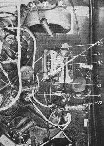
Fig. 6 - After the first i.f. transformer is removed, the
mechanical filter subassembly is installed, and held in place by two screws. The
board should be made small enough to pass through chassis opening.
Construction
The only parts you will need, in addition to the
mechanical filter, are two 10,000-ohm, 1/2-watt resistors, CR1 and R2), two 0.001-μf.
ceramic disc capacitors (C1 and C2), a 1" x 1" piece of Vectorbord or other suitable
material, six push-in terminals, and an L-shaped mounting bracket.
Except for the removal of the first i.f. transformer, all components and connections
in your receiver or transceiver remain the same. A typical circuit before modifications
is shown in Fig. 2. Variations in component values or in i.f. transformer design
in different receivers are not critical and will not adversely affect the installation
of the filter. Figure 3 shows the same portion of the receiver after the filter
has been installed.
The actual filter and additional components are mounted on a subassembly as shown
in Fig. 4. While it is not necessary to shield the filter - its components
are already housed in metal cans which have been grounded to the printed circuit
board - it is necessary to have a good ground connection between the board and the
receiver's chassis.
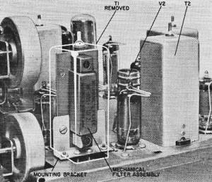
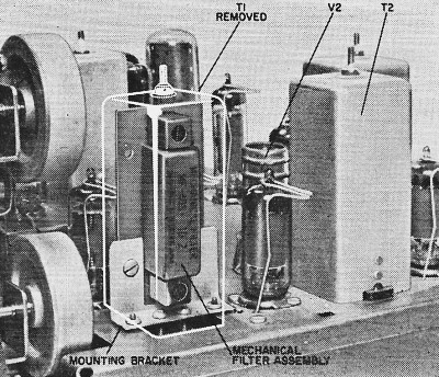
Fig. 7 - Above-the-chassis view of mechanical filter mounted
in place of T1. Insertion loss is on the order of 1.5 to 3 db.
The one-inch-square piece of Vectorbord is bolted to the bottom of the L-shaped
bracket. Resistors R1 and R2 and capacitors C1 and C2 are mounted on the board.
The push-in terminals serve to hold the components and the connections to the receiver.
Before and after photos show how the subassembly is mounted on the chassis. Check
to see that the board fits in the chassis opening, to fully seat the bracket.
Alignment
Generally, once the filter assembly has been installed,
no further alignment is necessary. However, you might try to peak the remaining
i.f. transformers in the receiver. Just in case the two transformers on the filter
have been diddled with, they too should be aligned for maximum output at the designated
intermediate frequency.
Posted March 26, 2024
(updated from original post
on 5/25/2018)
|