|
February 1972 Popular Electronics
 Table of Contents
Wax nostalgic about and learn from the history of early electronics. See articles
from
Popular Electronics,
published October 1954 - April 1985. All copyrights are hereby acknowledged.
|
RF, IF and baseband amplifiers;
RF, IF, and baseband filters; fixed and tunable local oscillators, single- and double-balanced
mixers, attenuators, envelope detectors and phase detectors, directional couplers, power
combiners and dividers, et cetera, are all component types used for receiver systems
regardless of whether vacuum tubes or transistors comprise the active parts. In 1972
when this article appeared in Popular Electronics magazine, people were beginning to
get comfortable with the idea of transistorized products replacing the familiar tube.
Instant-on televisions and radios were a welcome innovation made possible by transistors
that needed no warm-up period. The introduction of integrated circuits (IC's) for some
of the low frequency functions like IF (intermediate frequency) and baseband (BB) led
to smaller size, lower power, more lightweight, and less expensive gear - usually with
greater capability and improved reliability.
Fundamentals of Solid-State Receivers
New semiconductors, new IC's, and new circuits make much better receivers possible
By Jim White, W5LET
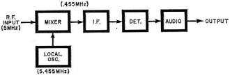
Fig. 1 - This is a simple single-conversion superheterodyne as used
in most receivers. The i-f is 455 kHz, which is somewhat standard, but other frequencies
could be used.

Fig. 2 - Double conversion superhet uses a crystal-controlled first
local oscillator and a variable second for actual tuning. Image rejection is better than
in single-conversion type (above).

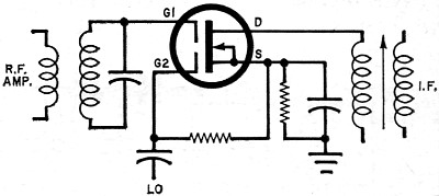
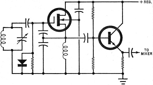
Fig. 3 - Here, the dual-gate MOSFET r-f stage has its gain controlled
by a negative voltage which shown is applied to gate 2.
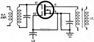
Fig. 4 - This mixer also uses a dual-gate MOSFET, with the local oscillator
signal applied to gate 2 of the transistor; r-f on gate 1.
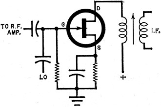
Fig. 5 - This circuit shows how a junction FET can be used as mixer.
There is less isolation than when the dual-gate MOSFET is employed.
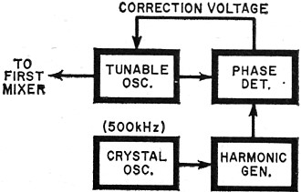
Fig. 6 - This tunable oscillator is locked to harmonic of crystal
frequency and kept on frequency by the action of the phase-locked loop.
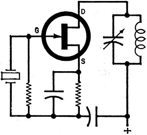
Fig. 7 - Typical crystal-controlled oscillator using a junction FET.
The tuned circuit in the drain is set to the crystal frequency. For a different frequency,
both crystal and the tuned circuit components must be changed.

Fig. 8 - This tunable circuit is used as second local oscillator with
a buffer stage to provide isolation from the mixer circuit.
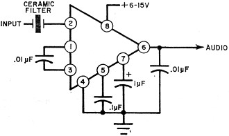
Fig. 9 - This IC i-f stage provides 0.8 volt output from an input
as low as 50 microvolts. The circuit also has agc range of 60 decibels.
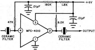
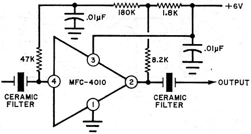
Fig. 10 - The integrated circuit used in this i-f strip costs only
$1.50 and provides 70 dB gain at 455 kHz.
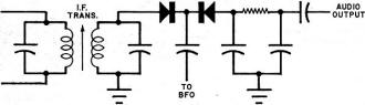
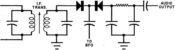
Fig. 11 - This simple product detector for CW and SSB applications
uses a back-to-back dual diode arrangement.
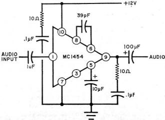
Fig. 12 - There are many available integrated circuit devices that
can be used in the audio amplifier stage. Some will provide up to 5 watts output.
Receivers, like almost every other kind of electronic equipment, have grown increasingly
complex - primarily because people expect so much more of them in terms of performance
and versatility. Almost all of the bands, commercial and amateur, are getting so congested
that selectivity poses a real problem in the design of a good high-frequency receiver.
Single sideband, with all of its advantages, has brought with it the need for stability
far greater than that required for conventional AM. And, to top it all off, everyone
wants receivers that are smaller and more compact.
The appearance of the transistor provided the answers to some of these problems. Space
and weight could be trimmed significantly, while heat, long one of the big enemies of
electronic equipment, could be almost eliminated. However, transistors had problems of
their own - leaving a lot to be desired as far as stability, overload, and circuit design
were concerned.
Then along came integrated circuits and field effect transistors. The IC brought more
space reduction and, in some cases, simplification of circuits. The FET has solved many
of the overload problems connected with bipolar transistors. The FET high input impedance
has almost eliminated loading of tuned circuits, resulting in higher Q's and improved
selectivity; and the low noise of FET's has improved sensitivity. So it is now possible
to design and build a solid-state receiver that is equal to, or even better than, its
vacuum tube counterpart.
Most electronic experimenters choose to buy factory built receivers because they feel
the task of constructing one is beyond their capabilities. This is not necessarily the
case. They build many other electronics projects that are just as complicated. Perhaps
a better understanding of just how a solid-state receiver is designed and how it works
would cause many to try constructing one for themselves.
The Basic Superheterodyne. A block diagram of the basic superhet
system is shown in Fig. 1 - applicable to simple BCB units, FM receivers, CB rigs, radio
control, etc.
Assume that the input circuit of the mixer is tuned to 5.000 MHz. A local oscillator
built into the receiver is tuned to 5.455 MHz and is coupled to the mixer. When a nonlinear
device has two such signals fed into it, there are four signals at the output: 5.000,
5.455, 10.455 and 0.455 MHz. By following the mixer with a selective tuned circuit and
amplification (the i-f amplifier) at the difference frequency (455 kHz) considerable
improvement in selectivity can be achieved as opposed to the mere amplification of the
5.000-MHz signal alone. Why? Because the higher the frequency of a tuned circuit, the
less selective it becomes. For this same reason, the sum frequency (10.455 MHz) was passed
over.
Double Conversion. In considering the layout in Fig. 1, a logical
question arises: Why not move the local oscillator frequency nearer to that of the received
signal? This would lower the frequency of the i-f amplifier and provide even more improvement
in selectivity. This is true; but, as the i-f frequency is lowered, problems of another
nature arise.
The mixer is not selective enough to attenuate all signals other than 5.000 MHz -
especially those close to 5.000 MHz. If, for example, a strong signal at 5.910 MHz appears
at the input, it too will mix with the local oscillator frequency and will also produce
a difference frequency of 455 kHz. This will be amplified in the i-f amplifier, producing
what is called an image of the other 455 kHz. Images can appear anywhere in the tuning
range of the receiver.
Thus, it can be seen that moving the local oscillator frequency closer to the received
signal brings the images closer and makes it more difficult for the tuned circuits to
attenuate them. Adding more tuned circuits between the antenna and the input to the mixer
will help, and this is one reason for adding an r-f amplifier. However, as receivers
are called upon to get signals of higher and higher frequencies, the number of tuned
circuits needed to solve the image problem becomes prohibitive.
One solution is to use double conversion as shown in Fig. 2. Now, with the same 5.000-MHz
input, the first local oscillator is tuned to 11.000 MHz; and the output of the first
mixer is 6.000 MHz, the difference frequency. The image frequency is now 17.000 MHz,
which is far enough away from 5.000 MHz to be attenuated.
To get a lower i-f frequency for better selectivity, the second mixer is fed by a
local oscillator at 6.100 MHz, and the difference frequency of 100 kHz is amplified and
detected.
In addition to solving the image problem, double conversion can be a real asset in
improving stability. An oscillator is always a source of frequency drift in a receiver,
and the higher the frequency, the greater the problem. In some double conversion receivers,
the first local oscillator is crystal-controlled for stability, and the second, working
at a much lower frequency, takes care of the tuning. Over-all stability is thus considerably
improved.
However, double conversion receivers are not without their drawbacks. Every time an
oscillator is added, chances of spurious responses increase considerably, so quite a
few single conversion receivers are still to be found. But, instead of a low i-f frequency,
they use a frequency as high as 9.000 MHz to reduce the image problem. The development
of excellent crystal filters for this frequency range has helped to solve the problem
of selectivity for these single conversion units.
RF Amplifier. An r-f amplifier is included in high-frequency receivers
for two main reasons: to increase the level of the antenna signal to a point where it
will override the noise generated in the mixer, and to offer discrimination to spurious
signals. Too much amplification can create problems with cross-modulation and blocking,
which can occur when one stage of the receiver (the r-f or mixer) is overloaded.
The circuit of an r-f amplifier using a dual-gate FET is shown in Fig. 3. The FET
works well as an r-f amplifier because of its excellent "square-law" behaviour, which
means that a frequency applied to its input appears at the output along with the frequency's
second harmonic - and no other harmonic. If the circuit is tuned (as in an r-f amplifier),
the second harmonic is of no importance since it will be eliminated. The square-law behaviour
of a FET is much better than that of a bipolar because the latter has characteristics
similar to a diode, resulting in more harmonics.
In the circuit shown in Fig. 3, the signal is applied to one gate of the dual-gate
MOSFET, while automatic gain control is applied to gate 2. This use of feedback to control
the gain on the second gate is one of the big advantages of the dual-gate FET. As mentioned
previously, the FET also has a high input impedance so that it does not load the tuned
circuit and it makes possible a very high Q to prevent spurious signals.
Mixer. As its name implies, the mixer stage takes two signals, mixes
them, and provides outputs which are the sum and difference of the two. By selecting
the proper output, a high frequency can be converted to a much lower one.
Any nonlinear device can be used as a mixer: diodes, bipolar transistors, or FET's.
Usually the diode is not used at lower frequencies because there is a signal loss in
conversion, and the characteristics of a bipolar limit its usefulness when handling strong
signals.
Here again, the dual-gate MOSFET is preferred - even over the junction FET or single
insulated gate FET. The second gate is used for the local oscillator input (see Fig.
4). With the r-f input on gate 1, the signal and the oscillator are well isolated. This
eliminates a problem called "pulling," which means that the tuning of the mixer causes
a shift in the frequency of the oscillator.
A mixer using a junction type FET is shown in Fig. 5. Like the circuit in Fig. 4 it
provides signal gain while converting the input to the i-f frequency (conversion gain),
but the isolation of the oscillator frequency is not as good as provided by the circuit
in Fig. 4.
Local Oscillator. In the simple super-heterodyne, the tuning range
of the local oscillator must maintain the difference between its own frequency and that
of the input so that the i-f frequency is always the prescribed amount - in the case
of the example used here, either 455 kHz above or below the signal. This frequency difference
must be maintained throughout the frequency range of the receiver if the i-f amplifier
is to pass and amplify (called "tracking") the mixer output.
Many modern double conversion receivers use a crystal-controlled first local oscillator
to improve stability at high frequencies. The second local oscillator, operating at a
much lower frequency is tunable. In addition to providing stability, this method assures
the same tuning range on all bands and makes calibration easier because the oscillator's
tuning range is the same on all bands. Several types of communications receivers used
by amateurs utilize this principle, and often as many as a dozen crystals are used in
the first local oscillator.
If more expanded coverage is desired, the designer must include more crystals and
a more complex switching arrangement. Some of the more expensive and complicated receivers,
designed to receive signals between 500 kHz and 30 MHz, have a first oscillator whose
frequency can be shifted, either by conventional tuning, or by band switching inductance
and capacitance. Such an oscillator normally would be too unstable, but in this case
it is phase-locked to harmonics of a very stable crystal oscillator. Though somewhat
more complex, this arrangement offers excellent stability, a reduction in the number
of crystals needed (usually only one or two), a much wider range of frequencies, and
simplified switching.
A block diagram of a phase-locked oscillator is shown in Fig. 6. A precision 500-kHz
crystal oscillator drives a harmonic generator, which provides good, strong harmonics
to frequencies well above 30 MHz. These harmonics, appearing at every 500 kHz, are fed
to a phase detector which also receives the output of the tunable oscillator. As long
as the tunable oscillator is at an exact multiple of 500 kHz, the output of the phase
detector is zero. However, if the oscillator drifts, the output voltage of the detector,
which is coupled to a variable capacitance diode connected across the oscillator tuning
coil, brings the oscillator frequency back to the correct value. With proper design,
a phase-locked oscillator has extremely good stability - even better than some crystal
oscillators operating at higher frequencies.
For those interested in a simpler approach, Fig. 7 is a crystal-controlled oscillator
using a junction FET. The circuit in the drain is tuned to the crystal frequency. For
multi-band operation it is necessary to switch crystals and tuned circuits.
As mentioned previously, many receivers have a tunable second local oscillator that
determines the frequency stability of the receiver. In the circuit shown in Fig. 8, a
buffer stage is included to provide more isolation and minimize "pulling" of the oscillator.
The oscillator uses a single-gate MOSFET, while the buffer is a conventional bipolar
transistor.
I-F Amplifier. No mention has been made so far about the use of integrated
circuits. Why? Simply because there does not seem to be any IC that equals the performance
(in the circuits discussed so far) of the devices suggested. With the i-f amplifier however,
it's a different story. There are several IC's available that certainly do an excellent
job here.
What do we expect the i-f amplifier to do? Amplify, of course; but it is here that
we seek to achieve much of the receiver's selectivity. It is possible to provide amplification
very simply with an IC; but selectivity must be added, usually in the form of a crystal
or mechanical filter. Recently, also, ceramic filters have been used and they offer some
advantages, especially in size and cost. A ceramic filter approximately 14" square and
3/4" long can be bought for less than $15 and it can be combined with an IC to make a
very good i-f stage.
Generally speaking, most crystal filters used today are of the higher frequency types
(up to about 9 MHz) and the mechanical filters are for lower frequencies (to about 500
kHz).
Space does not permit a description of all of the IC's that are available for an i-f
amplifier. One typical example, however, is shown schematically in Fig. 9. Designed for
AM use only, it provides 0.8 volts, peak-to-peak with inputs as low as 50 microvolts
at pin 2. It has an extremely good agc network as well as an AM detector. The agc range
(referred to pin 2) from 50 microvolts to 50 millivolts is 60 dB. The IC is in a TO-5,
8-pin case and with four capacitors and some means of achieving selectivity, it makes
a good AM i-f strip. The IC is an LM-372.
A schematic of an i-f strip built around a new, low-cost IC recently announced by
Motorola is shown in Fig. 10. It is extremely small, but provides a gain of up to 70
dB at 455 kHz. The IC is about $1.50.
Product Detector and BFO. Most modern receivers use one form or another
of a product detector for SSB and CW reception. To understand why a product detector
is desirable, we must review some basic facts about these two modes of transmission.
First, with both SSB and CW, something must be added at the receiving end to produce
audible signals. With CW we have a carrier, but no audio modulation. So an oscillator
is built into the receiver with a frequency very near the i-f. When the two are mixed
(beating against each other) a signal in the audio range is produced. It is the same
principle as in the mixer stage except that the output is an audio beat. Usually the
beat oscillator is variable in frequency so that the pitch can be varied to suit the
operator.
In receiving SSB signals, we must remember that the carrier was suppressed at the
transmitter so that the receiver must supply the carrier. This is done by the beat oscillator
operating with the sideband to produce audio. Just as with CW, the beat oscillator must
be positioned properly as far as frequency is concerned for best results.
Why a product detector? Because the regular diode detector most often used with AM
will introduce severe distortion unless a proper balance is maintained between the signal
and the beat oscillator. This is difficult to do. In most receivers lacking a product
detector, it is necessary to reduce the signal input with the r-f gain control. With
a product detector, which is really a mixer-type demodulator, the requirements as to
the ratio between the received signal and the beat oscillator is much less critical so
the audio is much "cleaner."
One very simple product detector circuit, with back-to-back diodes, is shown in Fig.
11. The beat oscillator must be stable and also. must have sufficient output. Because
of the need for exceptionally good stability in the BFO, many manufacturers use crystal-controlled
oscillators. Usually two crystals are provided so that the frequency will be correct
for either upper or lower sideband when receiving SSB.
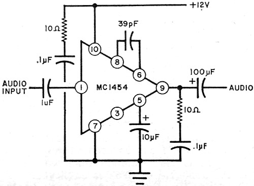
Audio Amplifier. The use of an IC in the audio portion of a solid-state
receiver is the only logical approach. There are many available to do the job. One possibility
is the circuit shown in Fig. 12. It uses a minimum of parts and operates with a 12-volt
input. An RCA unit uses a maximum of 9 volts. The General Electric PA-234 provides 1
watt; the PA-237, 2 watts.
Other Considerations. There are many other factors involved in the
design and construction of a solid-state receiver. Not all of them can be covered here,
but most of them have to do with mechanical details. For instance, it is almost imperative
to use printed circuit techniques, and the construction should be good and solid. The
power supply must be of the well-regulated, solid-state type.
Posted April 11, 2018
|