Module 16 - Introduction to Test Equipment |
||||||||||||||||||||||||||||||||||||||||||||||||||
|
Module 16 − Introduction to Test Equipment Pages i, 1−1, 1−11, 1−21, 2−1, 2−11, 2−21, 3−1, 3−11, 3−21, 3−31, 4−1, 4−11, 4−21, 5−1, 5−11, 5−21, 5−31, 6−1, 6−11, 6−21, 6−31, 6−41, Index
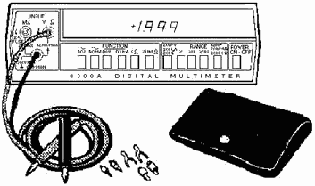
Accessories
A dc high-voltage probe is available for use with the multimeter. The probe extends the range of the multimeter in a safe and convenient manner. It is primarily used to measure high-voltage, low-power, dc- current sources, such as the anode supplies in television receivers and other cathode-ray tube circuitry.
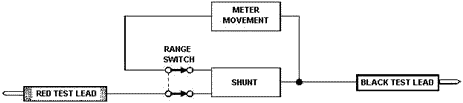
Figure 4-7. - Functional block diagram of dc current circuits.
Caution Do not use this probe on electrical equipment that can
deliver high power under short-circuit conditions, such as from a large dc motor-generator set.
Also available is an ac high-voltage probe. The 10,000-volt ac probe is similar to the high-voltage dc probe with the following exceptions:
· You take readings on the 0-10V AC scale and multiply by 1,000.
ELECTRONIC DIGITAL MULTIMETER
As you studied in chapter 3 (externally excited meters), placing a meter into a circuit causes energy to be taken from the circuit. The amount of energy taken depends on the sensitivity of the meter. In some cases, this energy loss cannot be tolerated. For example, in extremely sensitive circuits, such as oscillator grid circuits and automatic volume control circuits, degradation of normal circuit operation will occur. This often results in failure to obtain a usable indication of the fault. The use of electronic multimeters is practical in these sensitive electronic circuits. The higher the input impedance of a meter, the less the loading effect and the more accurate the measurements taken. Electronic multimeters have considerably greater input impedances than do nonelectronic multimeters.
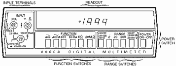
One example of a typical electronic multimeter in use within the Navy is the electronic Model 8000A Digital Multimeter. Most electronic digital multimeters overcome the disadvantage of requiring a continuous external power source by combining an external ac source with an internal rechargeable battery. Another advantage of this meter is that it can be read directly and does not use a scale. Figure 4-8 shows the model 8000A multimeter.
4-11
Figure 4-8. - Digital voltmeter 8000A operating features.
Operating Features
The locations of all controls, connectors, and indicators are shown in figure 4-8. The Input terminals, located on the left-hand side of the meter face, provide input connections for voltage or resistance (V-?) and milliampere current (MA) measurements with respect to the common terminal. The readout section, located across the upper half of the meter face, contains light-emitting diode (LED) indicators. They display the measured input and polarity signs for dc measurements. The Power switch, located on the lower right-hand side of the meter face, is a push-button switch used to energize the instrument. The RANGE switches, located on the lower, middle, right-hand portion of the meter face, select the voltage (200 millivolts, 2, 20, 200, or 1,200 volts), current (200 microamperes, 2, 200, or 2,000 milliamperes), and resistance (200 ohms, 2, 20, 200, or 2,000 kilohms) ranges. The Function switches, located on the lower, middle, left-hand portion of the meter face, select the voltage, current, or resistance modes. The MA input terminal is also a fuse holder for the current protection fuse.
Internal Battery Models
Power is supplied by internal rechargeable batteries that allow the instrument to operate for at least 8 hours. Recharging the batteries is accomplished by switching the Power switch to ofF and connecting the instrument to an ac power line. You can use the instrument when recharging the batteries on ac power, but the recharging time will be extended.
Q-5. Power for the electronic digital multimeter is normally supplied by what internal power source?
Overload Protection
An overload condition is indicated by the simultaneous flashing of the display readouts. The dc voltage function can withstand up to 1,200 volts dc or 1,200 volts root-mean-square (rms) on any range.
Q-6. How is an overload condition indicated by the electronic digital multimeter?
The ac voltage function can sustain up to 1,200 volts rms on the 20-, 200-, and 1,200-volt ranges and 500 volts rms on the 200-millivolt and 2-volt ranges. The current input fuse is protected above 2 amperes rms. Protection for the resistance function is to 130 volts rms in the 200-ohm and 2-kilohm ranges, and 250 volts rms in the 20-kilohm through 20-megohm ranges.
Basic Digital Multimeter Measurement
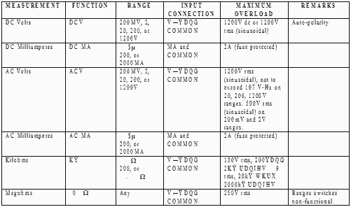
Table 4-1 lists the proper function push buttons, range push buttons, and input terminal connections for performing specific measurements with the model 8000A.
4-12
Table 4-1. - Basic Measurement Instructions
Block Diagram Analysis
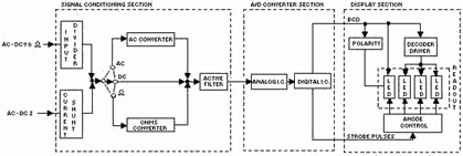
Figure 4-9 is a block diagram of an electronic digital multimeter. Note that the block diagram divides the instrument into three major sections: the Signal CONDITIONING section, the ANALOG-to- DIGITAL CONVERTER section, and the DIsPLAY section.
Figure 4-9. - Model 8000A block diagram.
4-13 The signal conditioning section provides a dc analog voltage, characteristic of the applied input, to the analog-to-digital converter section. This task is accomplished by the input voltage divider, current shunts, ac converter, active filter, and associated switching.
The analog-to-digital (A/D) converter section changes the dc output voltage from the signal conditioning section to digital information. The A/D converter uses a voltage-to-frequency conversion technique. a dc voltage at the input of the A/D converter is changed to a frequency by the analog integrated circuit (IC). This frequency is characteristic of the magnitude and polarity of the dc input voltage. Counting of the output frequency from the analog IC is accomplished by the digital IC. The resulting count is transferred in binary format to the display section. (Binary number systems are covered in NEETS, Module 13, Introduction to Number Systems, Boolean Algebra, and Logic Circuits.)
The display section takes the digital (binary) information from the A/D converter section, decodes it, and visually displays it. The decoded digital information is displayed on numerical LED readouts.
Q-7. In an electronic digital multimeter, the digital information is displayed by what type of numerical readouts?
Accessories
Several accessories are available for use with the electronic digital multimeter. One accessory is the test lead kit, shown in figure 4-10. The kit contains two color-coded test leads with threaded adapters. These adapters attach to banana plugs, pin tips, test prod tips, alligator clips, and binding post lugs.
Figure 4-10. - Test lead kit.
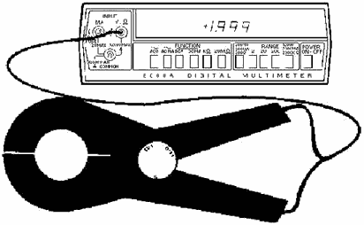
Figure 4-11 shows a high-current probe. This probe extends the ac current measurement capability from 2 to 600 amperes at frequencies up to 400 hertz.
4-14
Figure 4-11. - Ac high-current probe.
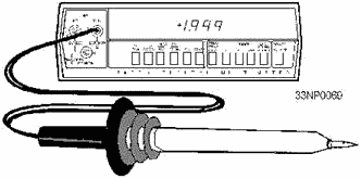
Figure 4-12 shows a high-voltage probe. The probe extends the dc voltage range to 30 kilovolts.
Figure 4-12. - High-voltage probe.
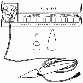
Figure 4-13 shows a high-frequency probe, which allows measurements over a frequency range of 10 kilohertz to 500 megahertz.
4-15
Figure 4-13. - High-frequency probe.
AC/DC Differential VOLTMETER
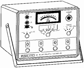
The Differential VOLTMETER provides extremely accurate voltage measurements and is a highly reliable piece of precision test equipment. Its general function is to compare an unknown voltage with a known internal reference voltage and to indicate the difference in their values. The differential voltmeter in common use in the Navy today is the model 893A (figure 4-14).
4-16
Figure 4-14. - Ac/dc differential voltmeter.
Q-8. What is the general function of the differential voltmeter?
The differential voltmeter can be used as a conventional TransistorIZED ELECTRONIC VOLTMETER (TVM) and a Differential NULL VOLTMETER. It can also be used to measure variations of a voltage near some known value (NULL DETECTOR), high resistance values (MEGGOMETER), and for dBm measurements.
METER DESIGN Characteristics
The differential voltmeter is a solid-state instrument that provides the capability of making dc voltage measurements from +/- 10 microvolts to +/- 1,100 volts. Ac voltages from 0.001 to 1,100 volts can be measured over a frequency range from 5 hertz to 100 kilohertz. Both of these measurements can be made without concern for loading the circuit. The differential voltmeter has four voltage readout dials that vary the resistance of the divider assembly as described above.
The differential voltmeter uses a built-in NULL DETECTOR to measure an unknown voltage. The meter circuitry compares the unknown voltage to a known, adjustable reference voltage supplied by the meter. The reference voltage is provided by a high-voltage dc power supply and decade resistor divider assembly strings that are set by voltage readout dials. In this way, the output from the high-voltage power supply can be precisely divided into increments as small as 10 microvolts. The readout dials are used to adjust the meter pointer to 0 and the unknown voltage is then read from the voltage dials.
A primary feature of the differential voltmeter is that it does not draw current from the unknown source for dc measurements when the measurement is obtained. Therefore, the determination of the unknown dc potential is independent of its source.
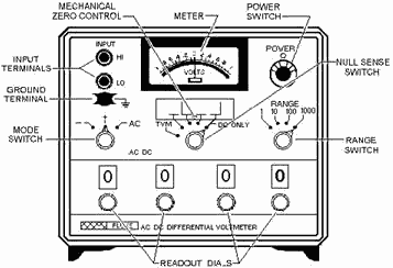
FRONT PANEL CONTROLS
The front panel of a typical differential voltmeter is shown in figure 4-15. With a few differences, the controls and terminals are similar to those used on other differential voltmeters. The NULL SENSE
4-17 switch selects the conventional TVM mode of operation and the various full-scale null detector sensitivity ranges when the instrument is operated in the differential mode of operation. The RANGE switch allows selection of the desired input voltage range, positions the readout dial decimal point, and selects the various ranges of the NULL SENSE switch. The readout dials provide a digital readout of the measured voltage when the instrument is in the differential mode.
Figure 4-15. - Controls, terminals, and indicators.
Modes of Operation
There are two primary modes of operation: the conventional transistorized voltmeter mode and the differential null mode. These modes are described in the next paragraphs.
Conventional Transistorized Voltmeter (TVM) Mode
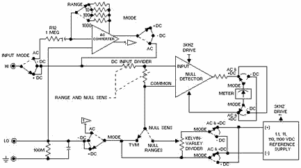
When the instrument is used as a conventional transistorized dc voltmeter, the circuitry is connected as shown in figure 4-16. The null detector drives the front panel meter and provides a full-scale meter deflection for any full-scale input. Positive or negative voltage measurements are made by reversing the meter terminals through the contacts of the Mode switch.
4-18
Figure 4-16. - Ac/dc differential voltmeter block diagram.
FunctionAL Block Diagram
Figure 4-16 is a functional block diagram of a differential voltmeter. The circuitry is made up of a reference supply, a resistive divider, a dc input divider, an ac converter, a null detector, and a meter. The circuitry is interconnected by various switching arrangements when you perform the desired ac or dc conventional or differential voltage measurements.
Placing the Mode switch in figure 4-16 to the AC position connects the instrument circuitry as a conventional transistorized ac voltmeter. a full-scale input voltage at the input terminals of the instrument results in a voltage being applied to the input of the null detector. The null detector drives the front panel meter that indicates the value of the measured ac voltage.
Differential Null Mode
When the instrument is used as a dc differential voltmeter, the Mode and NULL SENS switches in figure 4-16 are placed to their respective +/- dc and desired full-scale meter sensitivity positions. In this mode of operation, the NULL SENS switch selects a suitable resistance value to determine the full-scale sensitivity of the meter. The dc input voltage applied to the instrument is then compared with the null detector, and any resulting difference is used to drive the meter. The meter terminals can be reversed through the contacts of the Mode switch for +/- dc voltage measurements.
Transistor TESTERS
Laboratory transistor test sets are used in experimental work to test characteristics of transistors. For maintenance and repair, however, checking all transistor parameters is not necessary. a check of two or three performance characteristics is usually sufficient to determine whether a transistor needs to be replaced.
4-19 Two of the most important parameters used for transistor testing are the transistor CURRENT Gain (BETA) and the Collector LEAKAGE or REVERSE CURRENT (ICO). Two other tests that can be accomplished include the electrode resistance and diode measurements. You may want to review NEETS, Module 7, Introduction to Solid-State Devices and Power Supplies, for a review of transistors before continuing this section.
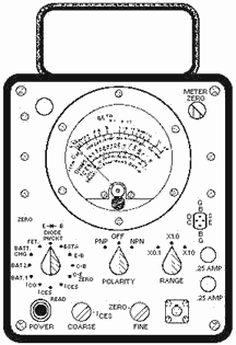
The Semiconductor Test Set AN/USM-206A (figure 4-17) is a rugged, field-type tester designed to test transistors and semiconductor diodes. The set will measure the beta of a transistor, the resistance appearing at the electrodes, and the reverse current of a transistor or semiconductor diode. It will also measure a shorted or open condition of a diode, the forward transconductance of a field-effect transistor, and the condition of its own batteries.
Figure 4-17. - Semiconductor test set.
To assure that accurate and useful information is gained from the transistor tester, you should make the following preliminary checks of the tester before testing any transistors:
1. With the POLARITY switch in the ofF position, the meter pointer should indicate exactly zero. (When required, rotate the meter ZERO ADJUST KNOB on the front of the meter to fulfill this requirement.) To prevent battery drain, be sure to leave the POLARITY switch in the ofF position when measurements are not actually being made.
2. Always check the condition of the test set batteries. To make this check, disconnect the test set power cord, place the polarity switch in the PNP position, and place the function switch first to BAT. 1and then to BAT. 2. In both BAT positions, the meter pointer should move so as to indicate within the red BAT box.
4-20
|
||||||||||||||||||||||||||||||||||||||||||||||||||