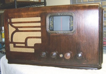
The Montgomery Ward Airline 62-437 "Movie Dial" Radio
(here is a sneak peek at how the story ends)
RF Cafe visitor Bob Davis, an RF Engineer with
Sensus - an automated meter reading
(AMR) design/production company, has long been involved in restoring old radios
in his spare time. Many of Bob's projects have been featured on the RF Cafe
Radio & Electronics
Restoration Projects page.
There are many websites that have photos of restored radios, but very few actually
have articles on how to go about the process. In an effort to inspire other people
to adopt the hobby and provide some insight into the kind of effort that can be
involved, Bob has provided this detailed write-up on the resurrection of his Montgomery
Ward "Movie Dial" 62-437 radio.
Sources for procuring old radios include antique shops, newspaper ads,
craigslist.org,
and of course
eBay.com.
Click on images for larger versions.
A Little History:
I purchased this item from a local consignment shop in early 2008 for 40 dollars.
When I first spied it, I had no idea what kind of radio it was, or the extent of
the damage to the inside chassis.

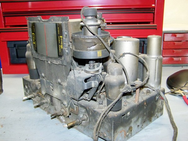
Movie Dial Film Strip - Badly Damaged

Chassis before restoration
Chassisfter restoration - note improved film strip

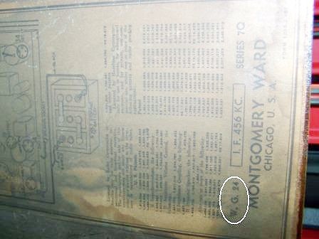
Tube Placement Diagram (W.G. = Wells Gardner)
The front of the radio intrigued me; it seemed to have a projection screen as
part of the tuning indicator.
After paying the consignment shop owner the 40 dollars to make it mine, I carted
it home and studied it further. Inside was a projection apparatus somewhat like
the "filmstrip" projectors they used to use long ago (when I was in school anyway).
The film portion of the device was badly damaged.
I removed the chassis from the cabinet and it looked like either the unit was close
to, or in a fire. Every square inch of the radio was covered in a dirty, greasy,
film that permeated every nook and cranny. In the picture below note that the chassis
is actually chrome plated!A normal collector or otherwise "sane" individual probably would have stopped
here, saved the tubes, and thrown the whole mess away. I guess I'm not one of those
two.
I carefully removed the tubes, cleaned them, tested them (only one was bad after
all of this!), wrapped them carefully and stowed them away for some later date when
I could roust them from their sleep once again.
The radio chassis unsheathed from its cabinet showed a lot of work was needed
if I it was ever going to play again. Over the next few months I researched the
unit, gathered as much data as I could, ordered parts, talked myself in and out
of actually trying to rebuild it, and finally got ready to dive into the "resurrection".
The radio is an Airline (Montgomery Wards) "Movie Dial" set from 1936 (if the
Rider's manual was correct for the model number of 62-437). It was a "farm" radio
meaning that it was not powered from the AC mains, but from a 6 volt rechargeable
battery. ( In 1936, much of the rural US had not been supplied with electricity
and battery powered tube sets such as these were the norm.) This radio is quite
special and high tech for the time as it utilized only one battery (other radios
of the period sometimes used two and three batteries to supply all the voltages).
Inspection of the tube placement diagram inside the radio yielded the initials
"W.G" which identifies this chassis was designed and manufactured by the radio wizards
at The Wells Gardner Company. Wells Gardner made sets for many catalog store companies
at the time. Look inside your 1930's vintage radio and see if you find the "W.G"
initials inside. Note also some of the stamp markings on this chassis which are
common to Wells Gardner radios of the period.
Companies like Montgomery Ward's would not only sell you the battery powered radio,
but also supply the battery. (Note: On earlier Philco sets you may find the words
"Philadelphia Battery Company". Many early sets were originally marketed to sell
batteries.) The catalog stores would also supply devices known as "wind chargers"
which would supply enough current from their wind driven generators to charge the
storage battery for the radio. (And you thought that "green" windmill generated
electricity was something new?) A number of windmill generators actually produced
quite a bit of power. There were several radios on the market, and other appliances,
that ran off of a 32 volt system comprised of batteries (usually 16, 2 volt cells)
and the wind chargers which could supply everyday electricity to a farmer who could
afford it. (Note: If you find a radio of this era, many of the battery sets have
similar plugs to those used for AC systems that were made to plug into these DC
systems. It is a common failure of those types of sets where unknowing people plug
them into the AC mains and not the 32 volt DC bus that they were intended for and
blow them up.)This particular model was only designed to run off of a 6 volt battery, and has
the clips to prove it.
The tubes needed a high B+ voltage to operate on and some negative bias for several
stages. Ingeniously designed, switching power supplies were used to accomplish the
conversion from 6 volts DC to the 150 or so volt high voltage rail the tubes needed
for operation. These "grandfathers” of today's solid state switching power supplies
were based on a vibrating set of switches with a doorbell buzzer type of motor which
rapidly opened and closed contacts connected to a battery and the primary of a transformer.
The switching rate was set by the mechanical design of the buzzer motor (or "vibrator")
to energize the primary of the transformer. This interruption of the DC current
from the battery, timed to the vibrator rate, produced a pseudo square wave across
the primary of the transformer or an "AC" waveform. The primary to secondary ratio
of the transformer then provided the necessary step up to the proper high voltage
needed for the radio's operation.

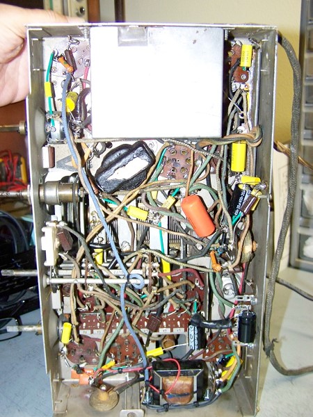
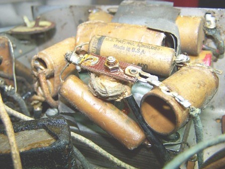
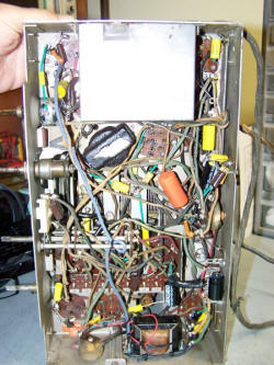
The business side of the chassis before restoration

All point-to-point wiring
The output of the transformer was treated differently depending on the power
supply design. Simpler units followed the transformer secondary with the usual rectifier
and smoothing capacitors found in most power supplies. The more complex ones, like
the one in the Wards unit here, used another set of vibrating contacts that worked
in harmony with the ones interrupting the primary of the transformer to interrupt
the proper side of the secondary at the same time. (I'll spare the reader all the
details here, search for synchronous vibrator power supply on the internet for further
reading. Kirt has recently posted a link describing their operation.) The output
was taken from the center tap of the secondary of the transformer, when filtered,
produced DC supply (read the references, you'll see why). This type of design negated
the need for a rectifier tube which saved the current draw associated with one prolonging
battery life. The down side of these designs were the complex vibrators needed to
produce them (which alas, were not made in large volumes and are getting harder
and harder to get) using split reed switches and a variety of other "tricks". (One
may adapt a simpler vibrator to perform this task by adding modern rectifier diodes
inside the can and some crafty circuit design and wiring).
Time to Diagnose the Patient:
It was time to look underneath the chassis and see what kind of restoration work
would need to be accomplished there. I gulped hard and took the following two pictures
which show the state of the chassis at that time.
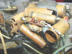
Note how buried some of the capacitors are: yikes! The three larger capacitors
at the bottom center are all replacements installed earlier in the sets life. Yes,
that is blood on the big electrolytic; the gremlins which killed this unit didn't
give up without a fight!
The usual suspects such as wax capacitors, dried out electrolytic capacitors,
frayed wires, and a whole lot of gunk appeared as I flipped the chassis over.
In the pictures above, note the large metal shield can over the vibrator power
supply to reduce EMI from that circuitry.
I decided to "divide and conquer" the work for the "resurrection" which I deemed
a better word than restoration which would infer that the radio had any chance of
working as-is at this time.
- Clean, clean some more, and clean again.
- Replace and rewire suspect parts and wiring under chassis.
- Rebuild the vibrator power supply with modern parts, especially replacing the
vibrator buffer capacitor.
- Locate, if possible, another "Movie Dial" filmstrip.
- Rebuild the top of the chassis.
- Get the radio turned on and working.
- Re-build and clean the projection assembly.
- Turn attention to the cabinet, clean it, and replace the grille cloth with a
suitable reproduction.
Cleaning Up the Chassis:
Audio Output Transformer Repair (lower right)

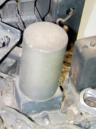
Vibrator power pupply
Point-to-point wiring

Point-to-point wiring (more)

Disemboweled Vibrator Power Supply Base
After disassembling the movie projector and placing all of its parts in a safe
place, I started cleaning the chassis as well as I could.
The first order was taking the whole chassis to the garage for a good dousing
of tuner wash and application of De-Ox-It to the variable resistors on the volume
and tone controls. I cleaned the main tuning capacitor contacts and lubricated the
ball bearings on the shaft.
I found completely disassembling the tuning capacitor mechanism to help. This
chassis has special insulators that isolate the tuner from the chassis that are
usually worn out. Luckily, one of my email friends pointed me to renovatedradios.com
which supplies replacements. The site also supplied knobs and other very useful
parts for the radio restoration hobby.
https://www.renovatedradios.com/parts.html
I found a bunch of paper towels, window cleaner, chrome polish, a degreasing
agent in water with a damp rag, and a whole lot of elbow grease turned out to be
the best approach for cleaning. I couldn't get all the rust off of the chassis,
so I neutralized it with Naval Jelly and then over sprayed it with a clear lacquer
to impede the rust from continuing its damage. (Believe me, there were times I was
imagining the chassis being hit by a Stinger missile having the best effect of all.)
I'll save the pictures of the results until later.
Replace and Repair Suspect Parts and Wiring Under the Chassis:
I replaced the usual suspects, all wax capacitors, all electrolytic capacitors,
and the out of tolerance resistors under the chassis. Where needed, terminal strips
were installed for added safety to accommodate the replacement of the electrolytic
capacitors and to un-do the other non-factory modifications added by others. New
cloth replacement wiring was installed where needed.
Note the "spaghetti" on the capacitor leads. I like to buy 18 to 20 GA Teflon
wire and strip it's insulation for "spaghetti". It doesn't melt or deform with the
heat of the soldering iron and should provide a long lasting repair.
Locate the audio output transformer at the bottom right of the picture. The tie
wrap was to strain relief a wiring repair I made internally to the transformer.
The transformer primary was open. Luckily, the break n the primary wire was where
the large lead from the chassis connected to the finer transformer wire. A little
micro surgery, a test with the Ohm meter, and it was good to go for another 70+
years. Just to make sure, I installed terminal strips which I connected the transformer
leads to. This will make sure that those leads are secured and take stress off of
them if the unit is moved for some reason.
Compare the following picture with the two presented earlier.
Rebuilding the Vibrator Power Supply with Modern Parts, Replacing the
Vibrator Buffer Capacitor.
Referring to the earlier picture, locate the shield can at the top of the picture
(which was taken after all of power supply rebuild was completed and I managed to
get all the parts safely back under the shield can). Under this shield lurked the
capacitors and inductors of the switching power supply.
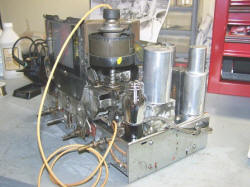
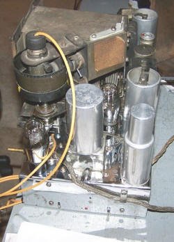
The vibrator sits on top of the chassis and connects to the rest of the supply,
and the transformer via a socket. It is shown below with its shield in place before
resurrection.
So what was under that shield under the radio? A fine example of point to point
wiring.
Undaunted by the intricate weaving, I took good notes, a lot of digital pictures,
and removed the transformer and the power supply from the chassis. The quarry was
the 0.01 μF capacitor ("buffer capacitor") located under the vibrator socket. The
picture below shows this capacitor before replacement.

There, That's Better
160.1 Volts Generated from a 6 Volt Input Supply - Success!
A Whole Lot of Work to Get Here.......
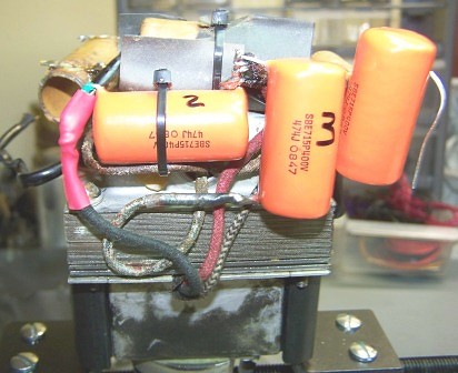
I replaced the buffer cap with a modern equivalent (1600V rating) and re-assembled
the vibrator socket to the transformer. It took a little shimming as the original
cap was just ever so slightly smaller in diameter than its replacement.
Next it was time to re-craft the rest of the supply and ready it for re-entombment
under the shield can. The picture below shows one of many intermediate steps to
get there.
After considerable weaving and re-attachment of all the parts of the power supply,
it was time to test to see if my labors were worthwhile (remember, I did not turn
on the vibrator before this time).
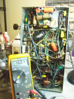
The (excuse the fuzziness) picture below was the result, success! (Note the rebuilt
supply installed in the chassis, with the shield removed and no tubes installed).
That voltage on the DMM is being produced by a 6 volt supply!
Seeing If it Would Play...
The power supply and under chassis work was completed. I went up top once again
and finished cleaning the chassis without the tubes installed. It was also time
to clean up the top side shield cans and perform other electrical repairs.
I wanted to see if the radio played before I undertook the resurrection of the
movie dial mechanism. I cautiously unwrapped the tubes so long ago put away and
installed them in the chassis. I connected the speaker, connected the 6 volt power
supply with a current limit of 2 amps and threw the switch.....
IT WORKED! I was a happy fellow.
Rebuilding the Movie Dial Assembly and Tuning Mechanism:
The movie dial assembly, projection screen, and all parts associated with it
were taken off the chassis long ago and filed away in shoe boxes under my bench.
I cleaned all of them as best I could and started to re-assemble the mechanism,
learning how it actually worked as I went.
Many of the mechanical parts of the tuning mechanism were seized up with the
crud, rust, and neglect they saw over their 70+ year life span. Two parts in particular,
the planetary dial drive and the spindle that holds the movie dial film, barely
moved.
The planetary drive allows the tuning mechanism to move at different speeds if
one is just flipping through the dial or making a fine adjustment to zero in on
a station.
The spindle mechanism which holds the movie dial film traverses up and down as
the band selector is actuated placing the proper portion of the film in the projection
lens showing frequency selected and other information. (This thing was totally seized
up!).
Thanks to my Renaissance man neighbor Harold, who is a fine machinist, we were
able to carefully take both of the assemblies apart, deduce how they operated, fix
them so they operated correctly, and re-assemble them. Be careful if you undertake
these tasks, both units have ball bearings in them that will fly everywhere once
you take them apart. Finesse and care is the key here (although I will admit the
spindle took more than a couple of carefully placed whacks with a hammer to free
up).
With all the pieces parts working and their true operation understood, I finished
cleaning all of the projection lenses, projection screen, and the inside of the
projector shroud.
The tuning mechanism was re-installed, a new dial cord strung, and tested thoroughly
awaiting the movie dial film to be installed.
Here's Where I Tell You I Was Very Very Very Lucky!
I had stared at the damaged movie dial film daily for a number of months prior
to rebuilding the radio wondering what to do. I made friends with a fellow (whose
name I won't use here to help him not get email floods looking for parts) who happened
to have a spare. I purchased the film from him for a fair price. I was a lucky man,
not only did he have a movie dial film, but one for my exact unit! There were several
frequency ranges for these sets, so I was very fortunate as they don't make reproductions
for these.
The email friend also was an invaluable source in my restoration of the vibrator
power supply and other issues along the way. It was very nice to have a friend who
had already restored the same radio! I would like to say (if he reads this) THANK
YOU VERY MUCH!
Putting Together the Completed Movie Dial:
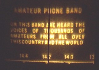
The "Movie Dial" in all its glory - illuminated by a 70-year-old
bulb

A Chrome Plated Chassis for a Sweet Ride
... Down Memory Lane
I installed the movie dial film, connected the 70+ year old Mazda bulb that illuminates
it, and adjusted the various focusing and aiming gadgets that make the display land
on the screen as it should.
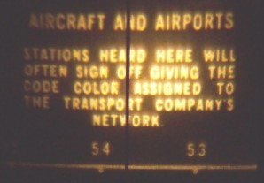
There is a semaphore color selector that rides on the bottom of the film holder
which, as the assembly goes up and down with the band switch, applies a different
display color for each band. I tried valiantly, but the old cellulose gel for each
color has long since gone from clear to translucent, blurring the display so that
is unreadable. Some day, when time permits, I'll try to polish the scratches out
of it so it's clear with some Novus polish, or replace the colors with modern gel
material. For now, I'll just move it out of the way and all bands will have white
annotation.
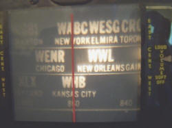
After a whole lot of tweaking and adjusting, SUCCESS!
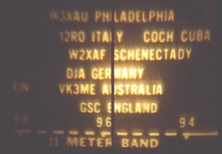
WWL is not at 870 KHz as it is today; in 1936 it was at a lower frequency. Note
how the dial is divided up for eastern, central, and western U.S. stations.
I was a happy fellow, this was the prize for all the hard work!
Final Chassis Integration:
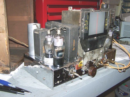
I finished cleaning and assembling the chassis with all the tubes. The pictures
below show a non-museum piece condition, but for me it looks as if it is made out
of gold. Notice the reflections of light on the bench and the mirroring of parts
on the bench by the chrome finish of the chassis.
The chrome plated chassis came out pretty well, despite all the crud I had to
take off of it and a lot of time to do just that.
Finishing It Up:
My Finished Masterpiece (original
wood finish... Damn it , man, I'm an EE, not a carpenter!)
After re-aligning the radio across all bands and checking for best operation
it was time to put the unit back into its case.
The grille cloth the radio originally came with was dry rotted years ago, so
I installed a new cloth that I purchased off the internet. I also cleaned the cabinet
but decided not to restore it at this time (there was a vain attempt at refinishing
this cabinet at some point in its life and I didn't want to open up a can of worms
right now. The idea for the short term is to enjoy the radio and show it to my friends.).
Again, not museum quality, but OK for me.
The four knobs from left to right are tone, band select, tuning, and volume.
The button in the middle turns on the lamp which illuminates the movie dial. This
is a battery operated radio and the lamp itself draws about an amp at 6.0 volts
adding unnecessary battery drain once a station is selected. The tuning knob is
original, but its color is slightly different as it came from another identical
set (thanks again to my internet friend!).
Having Fun With It:
I strung up a 50 foot antenna in my shop and have had many nights of fun working
DX with the old movie dial. It is as a selective and sensitive radio as any I've
encountered, from any era and technology.
I'll leave you with a few pictures from the movie dial and with best wishes and
a thank you for reading this. Many thanks to Kirt Blattenberger for putting this
up on his site.
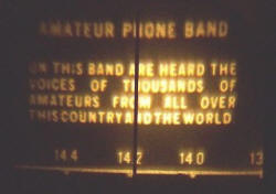
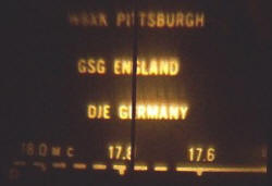


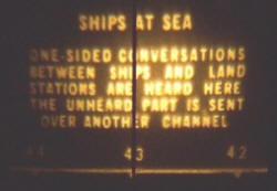
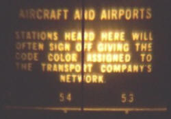
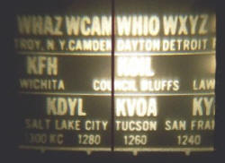
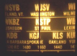
"Movie Dial" Images
|