|
   There
is a frequency region between around 400 MHz and 1500 MHz where the self-resonant
frequencies of discrete components make filter design very difficult, and where
the physical dimensions of transmission lines and cavity filters are too large for
practical implementation. There
is a frequency region between around 400 MHz and 1500 MHz where the self-resonant
frequencies of discrete components make filter design very difficult, and where
the physical dimensions of transmission lines and cavity filters are too large for
practical implementation.
 One of the most prominent ISM bands (900 MHz)
falls squarely in the middle of the region. Thanks to the wireless revolution, there
are a plethora of SAW and dielectric filters available for the 840 – 980 MHz
band, but that is about it, and they are only rated for relatively low powers (maybe
+20 dBm). Helical filters fill that gap nicely, and are a combination of all
three formats. One of the most prominent ISM bands (900 MHz)
falls squarely in the middle of the region. Thanks to the wireless revolution, there
are a plethora of SAW and dielectric filters available for the 840 – 980 MHz
band, but that is about it, and they are only rated for relatively low powers (maybe
+20 dBm). Helical filters fill that gap nicely, and are a combination of all
three formats.
Like cavity filters, the Q of the helical resonators is very high if constructed
properly. That is because at the frequencies of operation, the skin thickness is
getting very small and most of the current is flowing on the surfaces. Plating the
cavity walls and helix with a high conductivity material increases the Q even more
that bare of tinned copper.
Coupling to the helical coil is typically done with a direct contact wire tap
near the bottom of the coil, or via a non-contacting inductive coupling coil located
underneath the helical coil.
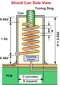
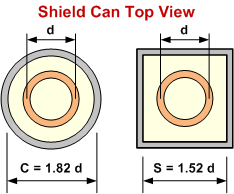
| A Helical Cavity Calculator is included in RF Cafe's
Espresso Engineering Workbook (free). |
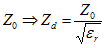
For air (εr=1)
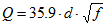


 |
d = Mean helix diameter (cm)
C = Inside diameter of circular shield (cm)
S = Inside length of square shield side (cm)
H = Height of shield (cm)
f = Resonant frequency (MHz)
Q = Unloaded Q of an air-filled resonator
N = Number of turns on helix
p = Helix pitch (turns/cm)
Z0 = Characteristic impedance of air-filled helical transmission line
(Ω)
g = Wire diameter and also space between turns (cm)
|
| |
|
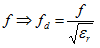
When the resonator is entirely filled with a dielectric (other than air,
εr=1), these parameters
are substituted as shown here:
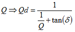
tan(δ) = Loss tangent of dielectric material
εr = Relative dielectric
constant of material
Zd = Characteristic impedance of dielectric-filled helical transmission
line (Ω)
Qd = Unloaded Q of a dielectric-filled resonator
|
Zverev was the first to publicly publish
the equations for helical filter design. While the book goes into more detail, the
basics of those equations are replicated here, and should serve as a good enough
springboard to get you going on a design. I actually worked with, but did not design,
a multi-cavity helical filter as part of a transmitter for a remote utility meter
reading transponder back in the early 1990s, produced by Itron. Choosing shield
and helix sizes is largely an iterative task once you know what the resonant frequency
for each cavity will be.
These graphs illustrate how the equations are affected when the diameter of the
helix, d, is varied. Notice that the wire diameter, g, increases with frequency
so that an adjustment of the helix diameter, d, is needed to keep the wire size
and space between the turns reasonable.
Sorry, but I do not have equations for the tuning slug's diameter or how it affects
the resonant frequency as it is advanced into the helix. A wag would be that if
the outside diameter of the tuning slug is very close to the inside diameter of
the helix, then the resonant frequency is modified as if the total height of the
helix and shield are shorter than when the tuning slug is fully retracted.
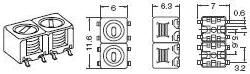
Example of a commercial Helical Filter by Toko Type 5CHW, 450 MHz.
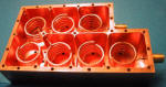
Custom 7:1 Helical Filter Assembly "High Performance Helical Resonator Filters"
by Ming Yu and Van Dokas.
Posted September 21, 2023
(updated from original
post on 2/15/2009)
|