 Circular
waveguides offer implementation advantages over rectangular
waveguide in that installation is much simpler when forming runs for turns and offsets - particularly when
large radii are involved - and the wind loading is less on a round cross-section, meaning towers do not need to
be as robust. Manufacturing is generally simpler, too, since only one dimension - the radius - needs to be maintained.
Applications where differential rotation is required, like a rotary joint for a radar antenna, absolutely require
a circular cross-section, so even if rectangular waveguide is used for the primary routing, a transition to circular
- and then possibly back to rectangular - is needed. Circular
waveguides offer implementation advantages over rectangular
waveguide in that installation is much simpler when forming runs for turns and offsets - particularly when
large radii are involved - and the wind loading is less on a round cross-section, meaning towers do not need to
be as robust. Manufacturing is generally simpler, too, since only one dimension - the radius - needs to be maintained.
Applications where differential rotation is required, like a rotary joint for a radar antenna, absolutely require
a circular cross-section, so even if rectangular waveguide is used for the primary routing, a transition to circular
- and then possibly back to rectangular - is needed.
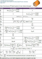 Calculations
for circular waveguide requires the application of Bessel functions, so working equations with a cheap calculator
is not going to happen. However, even spreadsheets have Bessel function (Jn) capability nowadays, so
determining cutoff frequencies, field strengths, and any of the other
standard values associated with circular waveguide can be done relatively easily. The formulas below represent
those quantities most commonly needed for circular waveguides. Please see the figure at the
upper left for a, Φ, x, y, and r variable
references. Calculations
for circular waveguide requires the application of Bessel functions, so working equations with a cheap calculator
is not going to happen. However, even spreadsheets have Bessel function (Jn) capability nowadays, so
determining cutoff frequencies, field strengths, and any of the other
standard values associated with circular waveguide can be done relatively easily. The formulas below represent
those quantities most commonly needed for circular waveguides. Please see the figure at the
upper left for a, Φ, x, y, and r variable
references.
Note: I received the following note from Brian Sequeira,
of the Johns Hopkins University Applied Physics Laboratory. "I reviewed tables on rectangular and circular waveguides,
and based on my experience of what confuses first-time readers and what does not, I made adjustments to notation &
symbols, corrected a couple of sign errors, and put expressions in a form that make their units more apparent."
The table for circular waveguide can be viewed full-size by clicking on the thumbnail to the right. Brian also
provided a table for rectangular waveguide.
| Hz |
 |
0 |
| Ez |
0 |
 |
| Hr |
 |
 |
| Hϕ |
 |
 |
| Er |
 |
 |
| Eϕ |
 |
 |
| βnm |
 |
 |
| Zh,nm |
 |
|
| Ze,nm |
|
 |
| kc,nm |
 |
 |
| λc,nm |
 |
 |
| Power†† |
 |
 |
| α† |
 |
 |
†
|
| The expression for α is not valid for
degenerate modes. |
| Equations derived from "Foundations for Microwave Engineering, R.E. Collin, McGraw-Hill
|
| †† Thanks to Patrick L. for finding error where
"4" in denominator should be "2." |
Values of pnm for TM Modes
| 0 |
2.405 |
5.520 |
8.654 |
| 1 |
3.832 |
7.016 |
10.174 |
| 2 |
5.135 |
8.417 |
11.620 |
Values of p'nm for TE Modes
| 0 |
3.832 |
7.016 |
10.174 |
| 1 |
1.841 |
5.331 |
8.536 |
| 2 |
3.054 |
6.706 |
9.970 |
Related Pages on RF Cafe
|


