Radio Amateur Course - How the Vacuum Tube Works
|
|||
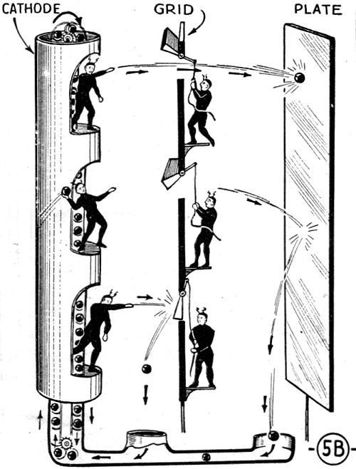
A while back I was using the familiar analogy that relates water pressure, hose diameter, and flow rate to electrical voltage, resistance, and current, respectively†, in an explanation to my daughter regarding why the water characteristics in her house changed after the well supply pipe and indoor plumbing changed. The cause, I proposed, was due to an increased distance between well and house, and the use of the plastic PEX tubing with a smaller inside diameter than the old copper pipe, respectively. The submersible pump and holding tank still supply the same 50 psi as before, but since that pressure now has to force the water through a path inside the house with more resistance to water flow, the delivery rate to fixtures is now lower. When I hold the contacts closed on the pump control relay, the most I can get is about 55 psi. Raising the pressure will require replacing the submersible pump, which is probably a good idea since it is a 115 volt, ½-HP job sitting about 100 feet down in the ground. A 1-HP version that operates on 220 volts will be an easy swap since it can use the same size electric cable as the existing one (12-2). I mention all that because this article's author goes to great lengths to create mechanical analogies based on hydraulic systems and little elfin men throwing electrons around inside a vacuum tube. It's definitely a unique approach, and the drawings are pretty good to boot! See Part 1, Part 2, and Part 3 Radio Amateur Course: No.2 - How the Vacuum Tube Works
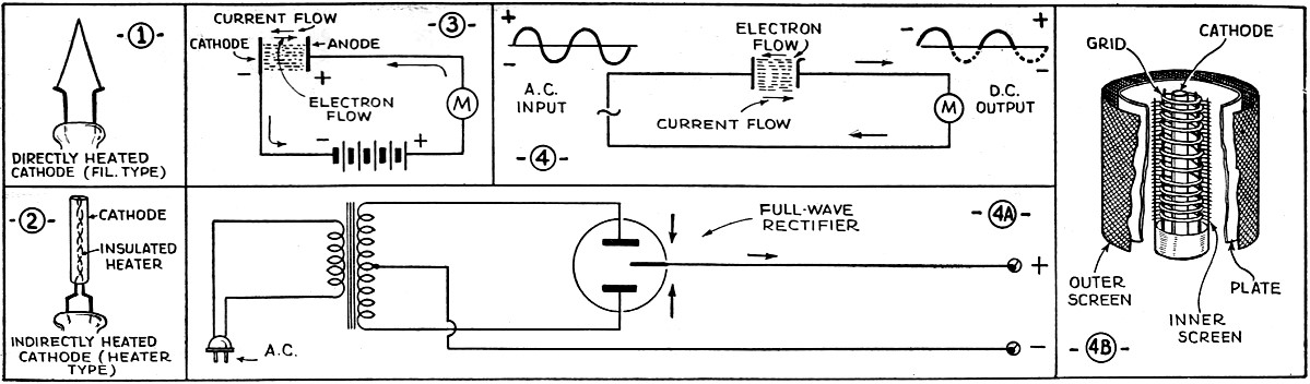
The entire radio industry as it stands today, owes its success and magnitude to the electron tube, or vacuum tube, if you prefer; the well-known bulb which is used in every type of present-day radio. The electron tube is not only used today for radio, but in other industries and serves a vast number of other purposes. For instance, with the aid of the photoelectric cell (a special form of vacuum tube) or electric eye, color measurements are made and it is possible to match colors perfectly with this instrument, where previously the entire matching of colors was dependent upon the human eye. It is the vacuum tubes used in radio, however, which we intend to discuss in this lesson. The starting point in the construction or analyzing the construction of the electron tube, is the source of electrons, which is technically termed the cathode. This cathode is made of a material which when heated gives off a quantity of electrons. In Fig. 1, we see the filament type cathode, wherein the wire used for constructing the filament contains a certain amount of material which will provide (emit) electrons when heated by an electric current passing through it. If this filament were exposed to the atmosphere and heated it would decompose or "burn out," as it is commonly termed. However, when enclosed in a glass envelope from which all air has been exhausted or removed, this filament will glow for a long time without damage.
Diagrams above-Figs. 1 to 4A, show filament and cathode heater units; how current flow is opposite to the electron flow (3); rectification of A.C. passing through an electron tube (4); hook-up of full-wave rectifier tube (4A); detail of tube elements (4B). In Fig. 2 we have what is termed an indirectly heated cathode, which consists of a small tube through the center of which is run the heating wire or resistor. The outside of this tube is usually coated with some metal oxide. When it is heated to a sufficient temperature, electrons are then emitted from the outside coating and it is entirely independent of the heater unit. As the electrons are emitted from this cathode they form what is termed an "electron cloud" around the cathode and within the envelope in which it is enclosed. These electrons can only be attracted to some object which is positively charged. Now, if we insert in this tube and around the cathode, a piece of metal or some other conducting material, and charge it positively, we can draw or attract the electrons to it. In Fig. 3 we show the action which takes place in a tube having a cathode and a plate or anode, as the plate is technically termed. By connecting a battery between the anode and cathode with the positive terminals of the battery connected to the plate, we attract electrons to this plate or anode. Current will then flow between the anode and cathode, remembering always that the current flow is also opposite to the electron flow. If we insert a meter in series with the circuit we will find that it will show the amount of current flowing in the circuit. This tube, as shown in Fig. 3, is known as the diode or one having two elements. If we remove the battery from the circuit and connect the negative side of the battery to the plate and the positive side to the cathode, no current will flow, because the negatively charged plate will reject the electrons. Effect of A.C. on Tube
The input circuit is indicated as alternating current while the output circuit shows current flowing in only one direction during half of the time of the input cycle. We have flowing in the output circuit then, an interrupted direct current or what would otherwise be termed half-wave rectification. All tubes of the diode type are therefore termed half-wave rectifiers. The 281 is an example of this type of tube. By using two anodes we can obtain full-wave rectification. This is shown in Fig. 4A. A rectifier of this type is termed a full-wave rectifier and an example is the 280 tube. Returning to Fig. 3 we can readily understand that as we change the degree of positive potential (voltage) applied to the plate, we will change the volume of electrons which are attracted to it. A low potential will attract a small amount of electrons, while a high potential or high voltage will attract a greater number of electrons. An important point to bear in mind is that a negative potential repels electrons, while a positive potential attracts them. (Unlike charges attract and vice versa.) How the "Grid" Works To have a better control over the amount of current flow in the plate circuit of the vacuum tube, we may insert a third element, known as the grid. Tubes having three elements are termed triodes, the prefix "tri" meaning three. This grid consists of a form of screen between the anode and cathode through which electrons must pass in order to reach the plate. This grid being located nearer to the cathode or source of electrons, will have a greater effect upon the electron stream when it is charged either positively or negatively. In Fig. 5, we have the same circuit as in Fig. 3, excepting for the addition of the grid. Because of the great effect this grid has upon the electron flow, it is called the control grid.
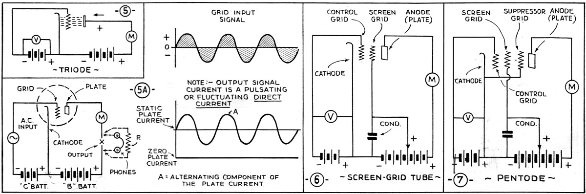
Fig. 5 shows action of triode tube; 5A, how A.C. input is changed into a rectified, pulsating direct current by an electron tube; 6, arrangement of the elements in a screen-grid tube; how elements are arranged in a pentode at Fig. 7. We may now apply either a positive or a negative potential to this grid and obtain a change in plate current or a change in the number of electrons reaching the plate, because if the grid is charged negatively, it will tend to repel or retard the flow of electrons between the cathode and the plate. This grid can be made so negative (biased) that it will entirely cut off the flow of electrons, reducing the plate current to zero. As this grid becomes more positively, charged, an increase in the flow of electrons to the plate will take place. That is, providing the potential (voltage) of the grid is not as great as that of the plate. As this grid becomes entirely positive, relative to the cathode, it will then collect a certain amount of electrons from the stream and return them to the cathode, causing current to flow in the grid circuit.
In Fig. 5a we show what happens when A.C. is applied to the input circuit of a triode, biased (bias usually means applying a fixed negative or positive charge, independent of the signal voltage, to the grid of the tube) so that the plate current is of fairly low value, but nowhere near the cut-off point. We show the input signal to the grid as alternating current, where it rises above and falls below the zero mark. As the input signal swings the grid more positive, or better stated - less negative - the plate current begins to rise above what is commonly termed the "no-signal" (static) plate current value; that is, the normal value of plate current with no applied signal. This constitutes one-half of the cycle of the input signals. On the other half of the input-signal cycle, the grid becomes more negative, causing the plate current to fall below its normal no-signal value. (See previous explanation under "How the Grid Works.") Now, in the plate circuit, we have apparently the same wave form as the input signal. The input signal was A.C.; however, A.C. does not flow in the plate circuit of the tube. This fluctuating replica of the input signal is termed the alternating component of the plate current. ("Plate current" is the current flowing through the circuit from plate to filament, or heater, when the electron stream is established by heating the filament.) If we were to connect earphones in series with the plate circuit, we would be able to hear the incoming signal reproduced and amplified in the plate circuit, that is if it was of low enough frequency to come within the range of the human ear. The fluctuating plate current or the alternating component of the plate current would cause the diaphragm of the earphone to vibrate due to the varying current flowing through the phones and the change in the magnetic pull on the diaphragm. So long as the voltage of the incoming signal does not exceed the value of the bias battery, there will be no grid current flowing, because the grid will never go completely positive. On the positive half of the input signal the grid, in reality, becomes just less negative. If we were to insert a resistor (R) in series with the plate circuit, the fluctuating current flowing through this resistor would cause a voltage drop across the resistor, varying directly with the plate current. The ratio of this varying voltage drop to the input signal voltage, is known as the gain of the tube or the voltage amplification. Tubes Have Capacity Between Elements In all types of vacuum tubes, we have in reality a number of small condensers in that there is a definite electrical capacity, for instance, between the plate and the grid, between the grid and cathode, and also between the plate and cathode, for the simple reason that each of these elements can be likened to the plates of a small condenser (current absorber). The grid to cathode capacitance is termed the input capacitance. The output capacitance is the capacity between the plate and cathode. In many very "high-gain" circuits, it is necessary to neutralize the plate to grid capacity in order that energy will not be fed back from the plate circuit to the grid circuit. The Screen-Grid This can be accomplished either by external methods of neutralizing, which will be explained in a later lesson, or by inserting a shield or a screen between "the plate of the tube and the grid. This is commonly termed the screen-grid and tubes having a control grid and a screen-grid, together with the anode and cathode, are termed tetrodes. This screen-grid is so designed that it will effectively shield the plate from the grid. While the plate to grid capacity of a triode may be as great as 8 mmf., the plate to grid capacitance of a screen-grid tube may be reduced to a value as low as 0.007 mmf. This screen must be constructed so that it will not materially obstruct" the flow of electrons between the cathode and plate; therefore, it is made in the form of wire mesh. It also must not be negatively charged because the flow of electrons would also be impeded. Therefore, a positive potential is in most cases applied to the screen-grid in order to accelerate the flow of electrons to the plate. This screen being an electrostatic shield must be bypassed with a condenser to the cathode in order to be grounded, in so far as high frequency currents are concerned. The voltage applied to the screen is usually lower than the plate voltage. The stream of electrons going to the plate being greatly accelerated by the screen-grid, may strike the plate at such a terrific speed that they will dislodge other electrons, which may be attracted to the screen, which is the nearest positively charged element. This is known as secondary emission and limits the output capabilities of the tube. This condition can be overcome by inserting between the screen and the plate another element which will not obstruct the flow of electrons to the plate but prevent them from returning to the screen. In order to accomplish this, the third grid or suppressor is usually connected directly to the cathode in order that electrons dislodged from the plate may continue back via the suppressor to the cathode. In some tubes such as the types 34 and 39 this suppressor is connected directly to the cathode of the tube internally. However, tubes such as types 57 and 58 have a separate pin on the base for this suppressor grid, in order that in special circuits a positive or a negative voltage may be applied to it. The values, of course, will be dependent upon the circuit requirements. In large transmitting tubes of the pentode type (pentode is a name given to all tubes having 5 elements), this suppressor is positively charged to the order of 30 or 40 volts.*
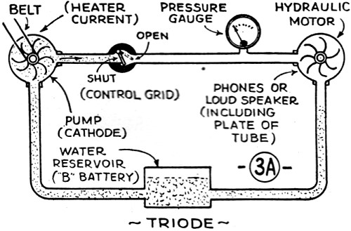
Hydraulic analogs showing action of half- and also full-wave rectifiers, the detector tube in a receiving circuit acting as a rectifier. The first diagram shows how a single-action pump and a check valve permits water to pass through the pipe up into the tank on each half stroke, while any counter water pressure is prevented from passing back into the pump by the check-valve. The second diagram shows how two half-wave rectifiers (pumps), with the aid of two check-valves cause a "full-wave" pressure to be developed in the main water line. When one is not working, the other is. *Some excellent books covering the electron theory and the operation of electron tubes are: "Electrons at Work," by Charles R. Underhill. "Radio Receiving Tubes," by Moyer & Wostrel. The RCA Tube Manual also contains a wealth of information covering the operation of various types of vacuum tubes. "Principles of Radio Communication," Prof. John H. Morecroft. "Modern Vacuum Tubes and How They Work," by Robert Hertzberg. † As a side note, a 100-foot-tall column of water in a 1" (i.d.) pipe weighs approximately [π(½")2 x 1200"] x [0.03606 lb/in3] = 34 pounds. Here is a useful paper on selecting a submersible pump with calculations incorporating depth, pipe resistance, pump flow rating, etc. Here are a couple articles on the electricity-water analogy: Electrical Quantities, December 1942 Radio-Craft
Posted September 22, 2020 |
|||

 This is the second lesson in the Radio Amateur
Course, which has been especially prepared for the readers of Short Wave Craft.
Future lessons will take up "inductance and capacity," and explain how oscillatory
circuits work.
This is the second lesson in the Radio Amateur
Course, which has been especially prepared for the readers of Short Wave Craft.
Future lessons will take up "inductance and capacity," and explain how oscillatory
circuits work.