Planes Can Land in Fog! Thanks to Short Waves
|
||
The Instrument Landing Systems (ILS) has been around since the early 1930s, as made apparent by this article in Short Wave Craft magazine. Frequencies, circuits, and infrastructure equipment have evolved over the years, but fundamentally, landing an aircraft (airplane, helicopter, dirigible) under 'blind' flying conditions has not changed. Two precision beams - one in elevation and one in azimuth - broadcast by ground-based installations are detected by airborne receivers and relative positions are displayed for the pilot's use in navigation. ILS does not help the pilot fly the aircraft; it only leads him to the runway threshold. In the past couple decades, space-based Global Positioning System (GPS) equipment has increasingly been used to replace ground-based microwave systems; however, in order to achieve necessary positional precision and fast-enough update rates, supplementary ground-based stations are needed to provide 'differential GPS' capability. Planes Can Land in Fog! Thanks to Short Waves Airplanes have been repeatedly landed while "flying blind" by the aid of this new short wave "landing beam", which has been developed by Uncle Sam's radio experts. This means that all airports will shortly be made "visible", even in a fog, thanks to short waves. By Lieut. Myron F. Eddy* U. S. N. Retired
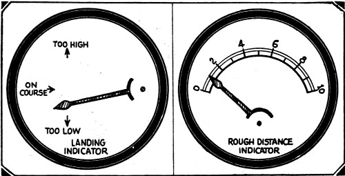
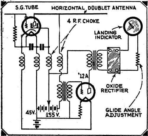
For the past three years the Bureau of Standards have been working on the short-wave landing beam for airplanes. Now they have it. The beam makes blind landings possible. The why and wherefore is most interesting. In the first place you realize that the blind flying of planes has been going on for some time. All the U.S. airways have radio-beacons that a pilot can follow from one airport to another, but suppose that he can't see an airport - how is he to land? The short-wave landing beam is the answer. And here is how it works. The regular airways radio beacon transmitter is located at one side of the airport - not on the airport. There is also another (marker) beacon, projecting a beam a short distance along the other side of the airport. But the beam transmitter is put right on the airport - right at the end of the landing runway. The pilot follows the airways beacon to the airport where he wishes to land. He knows when he passes over this beacon, because its signals change. Therefore, upon passing the beacon, the pilot turns left to the marker beam, straightens out on it, turns sharp left again and so hits the landing beam. He then turns left once more and follows the beam to a landing. It is as simple as "no right turns" and "one-way traffic" - sometimes simpler! The value of this system is obvious. It is literally a "life-saver". The landing beam .may be set at the airport in the direction of prevailing winds or any other, safe landing direction. It may be made steep, for a short approach, as in mountainous localities, or more gradual when a longer approach is desired. It can 'be, picked up at any altitude between 500 arid 5,000 feet. No manipulation on the part of the pilot is required since the tubing is fixed. He merely switches in his "landing-beam" receiver at the proper time. This receiver is visual and is mounted on the flight instrument board. If he keeps the needle on this instrument in the middle by controlling the plane's elevators, he will come in at a normal landing glide and level off without ever seeing the field. His altimeter will tell him when to cut the throttle completely; although he could hit with it partly on and do nothing worse than bounce. Landing Beam Operates on 3 Meters So much for the system; now about the apparatus. Remember that there must be control, or guidance, over three dimensions. For this reason a beam (called a "localizing beam") must be directed along the runway to form a lane, which will keep the pilot from swerving off the runway to right or left, while gliding down the landing beam. Also, the landing beam itself, although projected as a straight line (tangent to the horizontal runway) must guide the plane down a curved path, which becomes flatter and flatter near the ground end. This path is actually the line of equal intensity and is always below the axis of the projected beam. The landing-beam transmitter operates on about 3 meters. A directive antenna system is, of course, required; this consists of a number of short doublet horizontal antennas, which run perpendicular to the main supporting structure, which in itself is not high enough to be a flight obstruction. This whole outfit can be tilted and locked into position to give any desired angle above the horizon to the projected beam. The transmitter projecting the localizing beam along the runway operates on about 1,200 meters. It is a 200-watt set and uses small loop antennas. When signals from this beacon are picked up, the landing beam receiver aboard the plane is immediately switched on. There is a horizontal doublet type antenna about five feet long on the plane, employed for the short-wave landing receiver. The regular airways beacon receiver, either visual or aural, takes care of the airways beacon, the airport boundary marker beacon along the runway. The boundary beacon consists of a 50-watt transmitter feeding a loop-type antenna. Modulation of the radiated wave to the desired frequency, 1,000 cycles per second, is obtained by supplying the transmitting tube with a plate voltage of 1,000 cycles frequency. On the airplane, earphones connected in series with the main course indicator are employed with a special filter circuit. The boundary line is defined by a zero, as the plane passes over the boundary line; then an increasing signal as he comes within the landing-field area, On the airplane, the signal current in the output circuit of the special shortwave receiving set employed to receive the landing beam is first rectified and then passed through a landing beam "indicator". This "indicator" is mounted on the instrument board of the plane. To help in maneuvering onto the field a "rough distance indicator" has been developed which is also automatic. It works like the ordinary tuning meter, found on any receiver which has automatic volume control, and constantly indicates to the pilot the approximate distance of the plane from the localizing-beam transmitter. This transmitter is usually just back of the landing beam transmitter: and so the pilot usually "sets her down" just before the rough distance indicator registers zero - whether he feels like it or not! Otherwise he piles up on the transmitter antennas - if he does not see them at the last instant.
*AeronauTech Institute.
Posted September 23, 2020 |
||