Decimeter Waves - The Future of Radio
|
|
Millimeter waves (mm-waves) are the subject of a great many articles today describing advances being made in the part of the spectrum above 30 GHz (Ka and EHF bands, mm-wave); however, when this piece was published in 1935, it was decimeter waves - what is now referred to as UHF - that were the big to-do. Crowded frequency bands have been a problem since the beginning of radio because technology is constantly not only filling available bandwidth, but also pushing the frontiers higher. The advantage of going higher in frequency is that required bandwidths for existing modulation schemes represent a smaller percentage of the center frequency. For example, an 802.11b WiFi signal's 22 MHz bandwidth represents roughly 1% of its 2.4 MHz center frequency. 802.11a does 20 MHz at 5 GHz for 0.4%. Extend that center frequency up to 50 GHz and the channel occupancy is a mere 0.04%. That means for the same total band occupancy of 1% as with 802.11b, you can fit in 25 equivalent slots. The problem with going higher in frequency is that components are typically more costly and trickier to implement, and the power falls off faster with distance according to the familiar Friis equation. Decimeter Waves - The Future of Radio
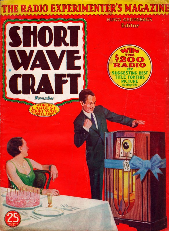
1 - Set of decimeter receiving antennas. 2 - Laboratory set up for the production of decimeter waves by means of a split Magnetron generator. 3 - Split Magnetron installed between the poles of an electromagnet. 4 - Pilot indicator instrument installed upon the bridge of a steamer. 5 - Portable decimeter wave transmitter with concentration mirror.
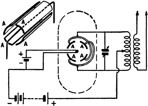
Schematic diagram of decimeter wave transmitter, operating with a split Magnetron tube.
How decimeter waves guide boat along course. By Eckard Klein The present article deals with some of the possibilities of waves only a fraction of a meter in length, the new "split magnetron" tube is described, also the manner of guiding a boat by means of decimeter waves. The great number of radio transmitters now in operation and the daily increasing demand for additional traffic channels, puzzles the radio commissioners of all nations, and has brought the present radio channel system to a point of practical saturation. Only by application of auxiliary tricks, for example the mutual use of one and the same wavelength by two transmitters, which operate in more or less large geographical areas, has it been possible to keep the world radio system in fairly smooth operation. These methods have or are actually hindering further progress in radio communication, however. The only hope of solving this problem lies in the belief that future research work in the wave range below 5 meters may unearth some heretofore unknown facts, which would enable us to utilize the great number of radio channels in this region for practical application. Despite the well-known fact that a great many of radio channels are unused in the decimeter* (one-tenth meter) range, no intensive research work had been carried on in Germany until about one and a half years ago. At that time the Radio Corporation of Germany (The Telefunken Co.) started secretly some very interesting experiments with decimeter waves of a length between 40 and 90 centimeters, which have furnished a great number of new facts about the character and the qualities of these very short waves. These very interesting experiments have indicated some new possibilities of decimeter wave utilization, which might in a short time to come be of incalculable value in the progress of radio communication. Since these very short waves can be bundled or concentrated like a light beam, and since, further, these waves are only receivable as far as the direct optical sight goes, it is possible to use them for a directed beam by which many transmitters and receivers may operate in parallel on the same wavelength without any mutual disturbance. The stumbling block in the utilization of these very short waves was until recently the enormous number of oscillations per time unit, amounting to many millions and even billions of cycles per second. It is easy to understand that currents of such a high frequency put insulation materials under a specially high electrical strain. Entirely new methods of handling these new high frequency electrical problems had to be designed; also brand new transmitter circuits never used before for the generation of these very short waves had to be developed. To produce these ultra high frequencies the so called "Haban-Roehre" (Haban tube) was used in Germany. This tube invented by the German radio engineer, Dr. Haban, is often called in England and America the split magnetron. As to the construction of such a magnetron tube let us note that this tube has an "inside" system, consisting only of a single cathode surrounded by an anode cylinder, but it possesses no grid. The anode cylinder (often called plate cylinder) consists of two main parts. Each of these main parts is further divided into two separate sectors, which are arranged opposite each other in the tube system. The cathode is therefore surrounded, as Fig. 1 shows, by a cylinder which actually consists of four different parts. Each pair of the oppositely positioned parts are electrically connected by means of small pieces of wire. An electro-magnet arranged outside of the glass bulb of the magnetron tube, produces a powerful electro-magnetic field which influences the tube in the direction of the cathode axis. In addition to the magnetrons very small triodes are used for the reception of the decimeter waves. These tubes bring to mind the American "Acorn" tubes and are of tiny dimensions. The system of construction is greatly concentrated so as to make the time of the electrons' transit practically zero. Another type of receiving tube also used for decimeter wave reception is the so-called "diode" type. These diode tubes, similar in their design to the diodes as applied in ordinary "broadcast" receivers, are of much smaller dimensions and are used as detectors. Experiments with these diodes have proved that they are well fitted for the reception of waves down to 40 centimeter in length. Used for Guiding Ships in Fog The practical application of the decimeter wave qualities for piloting of ships into foggy harbors was then demonstrated upon a large lake near Berlin, upon the so-called Mueggelsee. On the shore of this lake a transmitter was kept in operation radiating a twin-beam of decimeter waves. To demonstrate the useful effect of these waves, a small steamer had been equipped with two decimeter wave receivers. The steamer cruised about on the lake, until the two receivers installed aboard picked up both beam signals with about equal strength, and the ship then proceeded in a direction toward the transmitters on shore; directed only by a pilot instrument installed in front of the man at the wheel. This pilot instrument gave the wheelsman an exact indication as to how far the steamer had shifted outside of the "invisibly marked" lane. The accuracy of this piloting method was so great that it showed a strong indication on the piloting instrument when the steamer was only a few miles off the focal line of the twin-beam transmitter. Even in case the deviation was about 0.1 degree only the indicating instrument marked not only the shift but also the side toward which the ship has shifted. This has been further demonstrated during the experiments upon the Mueggelsee near Berlin. Two receivers operating on the same wavelength, and installed pretty close to each other, could be separately received without interference. The receiver could be turned in any desired direction. By turning this receiver in one or the other direction, either one or the other of the transmitters could be received, without being in danger of the slightest trace of interference from the transmitter not wanted. *Decimeter waves are here considered as those falling between roughly 0.1 and 1 meter.
Posted July 6, 2023 |
|