The Saga of the Vacuum Tube - Part 14
|
||
Here is Part 14 of a series entitled "The Saga of the Vacuum Tube," by Gerald Tyne, that appeared in Radio News magazine in 1944. Part 1 was printed in March 1943, and Part 22, the final chapter, was published in April 1946. It could have been a stand-alone book. If I manage to be able to buy issues with some of the other parts, those will be posted as well. You might be aware of the origins of the amplifying vacuum tubes, beginning with the accomplishments of Dr. de Forest and his Audion. As with most new technologies, progress moved very rapidly once other researchers glommed on to the concept. Here, Mr. Tyne discusses the development of the "Kenotron," "Pliotron," "Dynatron," and "Magnetron," by Drs. Langmuir, Dushman and Hull of the General Electric Laboratories, during the years 1913 to 1921. Note the Crosley Model 120 Senior Superheterodyne (Pliodynatron) implementation for the oscillator. See list of all 22 parts at bottom of page. The Saga of the Vacuum Tube - Part 14
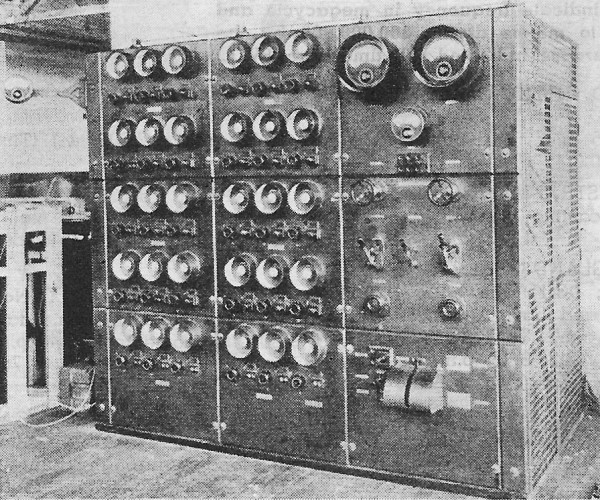
Fig. 155 - Pliotron Amplifier, using 30 "Type P" Pliotrons, used to modulate the 200 kw. Alexanderson alternator at New Brunswick in 1919. Photograph courtesy General Electric Company.
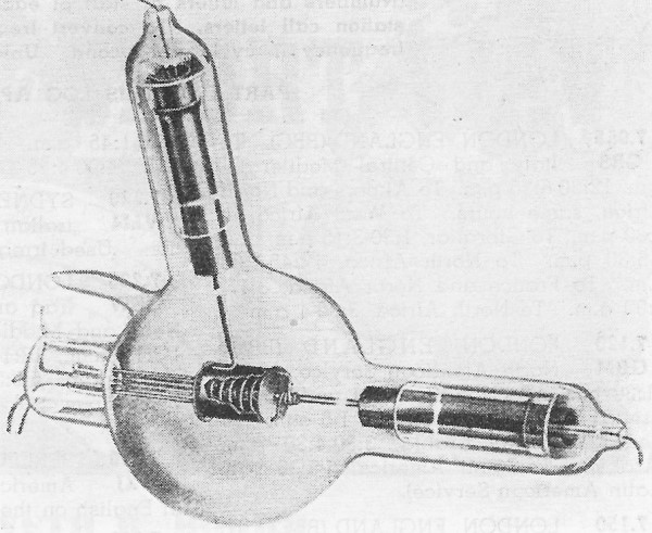
Fig. 156 - Hull's Dynatron vacuum tube, Reproduced from Proc. I.R.E., 1918.
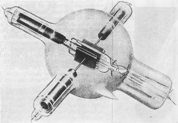
Fig. 157 - Hull's Pliodynatron vacuum tube. Reproduced frm Proc. I.R.E., 1918.
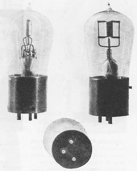
Fig. 158. Kenotron TB-1 vacuum tube. Photograph courtesy Bell Telephone Laboratories.
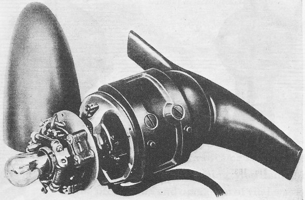
Fig. 159 - Wind-driven generator, showing TB-1 tube in mounting. Photograph courtesy Bell Telephone Laboratories.
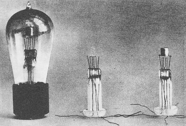
Fig. 160 - General Electric "Type G" Pliotron (VT-1-1, early CG-890). Left - completed tube. Center-filament and grid assembly. Right-complete assembly on stem. Photograph courtesy General Electric Company. By Gerald F. J. Tyne Research Engineer, N. Y. Covering the development of the "Kenotron," "Pliotron," "Dynatron," and "Magnetron," by Drs. Langmuir, Dushman and Hull of the General Electric Laboratories, during the years 1913 to 1921. In April of 1913 Langmuir and Dr. Saul Dushman of the General Electric laboratory attended a series of lectures delivered by Professor Wilhelm Wien at Columbia University. During their return trip to Schenectady they discussed the work which Langmuir and White had been doing and it was agreed that Dushman would take over that portion of the work on the new device which had to do with its use as a high-voltage hot-cathode rectifier and relay, and that White would continue to work on tubes for wireless and similar low-power applications. By June of 1913 Dushman had a three-electrode tube which was capable of operation, while still on the pump, at 20,000 to 40,000 volts on the anode and with a space current of 100 milliamperes. This tube had been exhausted to a high vacuum by means of a Gaede molecular pump. It was a bulb about 6 or 7 inches in diameter with side arms which contained the leads to the electrode terminals. The anodes were plates of sheet tungsten and the grid a spiral of 1.5 mil tungsten wire wound on glass supports. It was at first operated while still connected to the pump, but was then sealed off and became, in effect, a large power tube. After sealing off, it could be operated without blue glow at 10,000 volts on the anode and space current of 100 milliamperes. It was, on May 14, 1913, used to successfully accomplish what Alexanderson had in mind when he first brought the Audion to the laboratory; that is, to control the output of one of his high-frequency alternators. Still later it was used as a modulator in actual wireless tests. This single tube was later replaced by a bank of tubes, and in 1919 the 200 kw. Alexanderson alternator, installed at New Brunswick, was modulated through a magnetic amplifier by a bank of thirty Type "P" Pliotrons operated in parallel. Fig. 155 shows the amplifier used in this work. The anode voltage used was about 2300 volts and the anode current varied over the range 0 to 4 amperes. This represented a variation in modulating energy of about 4 kw. It was in November, 1913 that the need was felt for characteristic names for these new devices, and the term "Kenotron" was chosen for the pure electron discharge tube, and "Pliotron" for the pure electron discharge relay. The word "Kenotron" was derived from the Greek "kenos," signifying empty space (vacuum) and the ending "-tr-on" used by the Greeks to denote an instrument. Similarly "Pliotron" is derived from the Greek "pleion" signifying more. A Pliotron is thus an instrument for giving more, or an amplifier. It was the coining of these and other like words to describe later devices that provoked de Forest into dubbing them "Graeco-Schenectady." The first publication dealing with Langmuir's work came in October, 1913 when Langmuir read a paper in which he disclosed the method which he had used to prepare the electrodes and exhaust the tubes in such a way as to obtain a pure electron discharge. The paper was read at Columbia University and subsequently published.192 During the discussion which followed the presentation of this paper, Dr. H. D. Arnold brought out the fact that the 3/2 power law for the case of parallel plane electrodes had been published by O. D. Child in 1911,193 and that Lilienfeld had previously obtained the 3/2 power law experimentally and had published his results in 1910.194 Later Langmuir published two other papers in German publications. These later papers covered the same ground as his Columbia paper but went into somewhat greater detail.195, 196 The next publication was by Dushman in the General Electric Review and dealt with high-power rectifiers.197 The tubes described were high-voltage rectifiers (Kenotrons) exhausted to a pressure of 5 X 10⁻⁷ mm. mercury (0.0005 micron). Tubes which operated at voltages up to 100,000 volts and with space currents up to 100 milliamperes were described. Then in April, 1915 Langmuir presented to the I.R.E. his famous paper on "The Pure Electron Discharge and its Applications in Radio Telegraphy and Telephony.198 In this paper he gave the theoretical equations for the maximum space current between parallel plates, and for cylindrical structures. This equation came to be known, albeit somewhat incorrectly, as "Langmuir's 3/2 power law." He gave diagrams of the structures used in two of the types discussed, both of which had wire elements. He also disclosed that Dushman had succeeded in making Kenotrons for a voltage of 180,000 volts at a current of 250 milliamperes. Meantime Dr. Albert W. Hull of the General Electric laboratory also had been engaged in work on pure electron discharge devices. This first came to light when he presented a paper, on October 30, 1915, before the American Physical Society in New York.199 His work was somewhat unorthodox. The title of his paper was "Negative Resistance." He had succeeded in obtaining a negative resistance characteristic in the anode circuit of a three-electrode discharge tube by operating it with a positive voltage, higher than the anode voltage, on the grid. That is to say, he found a region of operation where an increase of anode voltage caused a decrease rather than an increase in the anode current. This device was dubbed the "Dynatron" and was described by Dr. Hull in a paper sent to the I.R.E. in January of 1917.200 This paper is probably the first to describe a four-electrode tube. One of these tubes, called a "Pliodynatron," is described and pictured in Hull's paper. Figs. 156 and 157, reproduced from this paper, show the "Dynatron" and "Pliodynatron" respectively. Dr. Hull continued his experimental work and some time later published a paper on the "Magnetron," the Graeco-Schenectady name for a vacuum-electric device which was con trolled by a magnetic field. Electrically it was a valve operated by a magnetic field. It was really a relay with no moving parts or inertia, the only limitation in speed of operation being the time necessary to build up the magnetic field. The Magnetron consisted of an evacuated tube of cylindrical shape with an axial filament and a cylindrical anode. The magnetic field was set up by an external coil surrounding the tube in such a way that the lines of force were parallel to the axis of the tube. The characteristics of this device were such that with constant voltage between anode and cathode, the current flow in the filament was not affected by a magnetic field weaker than a certain critical value, but fell to zero if the field was increased beyond this value. This was an extremely sensitive method of control. In fact, with proper adjustment the simple reversal of position of such a tube and coil in the earth's magnetic field is sufficient to completely cut off the space current. Dr. Hull gave the theory of this tube in a paper published in the Physical Review in 1921.201 and later in the same year described the tube and its possible applications before the A.I.E.E.202
Fig. 161 - General Electric "Type T" Pliotron, VT-12. During World War I a very large amount of development work was done in the field of radio transmission. Apparatus developed prior to the war rapidly became obsolete. It was appreciated by those in charge of development of apparatus for the Armed Forces of the United States that vacuum tubes played an important part in the equipment which must be provided. For such uses large quantities of these tubes were required, and a uniform interchangeable product was an absolute necessity. We have seen already that over half a million of these tubes were supplied by the Western Electric Company, some by the de Forest Company, and some by the Moorhead Laboratories. The General Electric Company also was called upon to produce such tubes and because of the research work of Langmuir and his associates, and because of their long experience in incandescent lamp manufacture, they were in an excellent position to do so. In fact, the General Electric Company supplied over 200,000 tubes to the Armed Forces, the great majority of which were manufactured and delivered in the year 1918. These tubes were, for the most part, manufactured at the Nela Park plant of the National Lamp Works of the Company at Cleveland, Ohio. The bulk of the General Electric tubes supplied to the Armed Forces during World War I can be divided into five types. The first of these is the Kenotron which was designated by the U. S. Signal Corps. as the "TB-1," of which approximately 4500 were supplied to the Signal Corps. This Kenotron was used in large numbers for regulation of the output voltage of the wind-driven generators used with airplane radio equipment. Because of the vibration to which they were subjected while in use, they had to be of extremely rugged construction. Fig. 158 shows three views of one of these tubes which, it will be seen, had a base of the three-contact type, and Fig. 159 shows a generator with the tube in place. The bulb was about 1 3/4 inches maximum diameter and extended upward from the base about 2 1/2 inches. The base was of the "Shaw Standard" type. The filament was made of tungsten wire, 3.15 mils in diameter. It had a total length of about 2 1/2 inches and was helical in form. The inside diameter of the helix was 0.145 inch and the pitch of the winding was 14 turns per inch. The anode was a molybdenum cylinder, 5 mils thick, 9/32 inch in diameter, and 5/8 inch long. The anode voltage varied under normal operating conditions but had a maximum value of about 250 volts. The maximum anode current was about 125 milliamperes. The filament operated at 1.45 amperes and the maximum filament voltage was 10.75 volts.
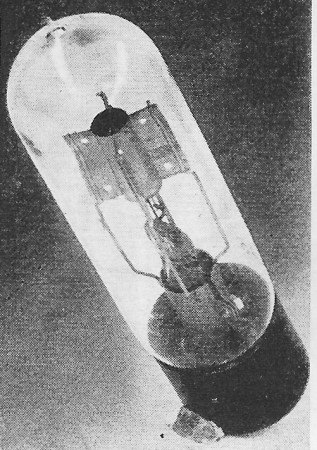
Fig. 162 - General Electric "Type U" Pliotron (CG-1144, VT-18). Photograph courtesy Bell Telephone Laboratories. The "Type G" Pliotron was used by both the U. S. Navy and the U. S. Signal Corps as a detector, amplifier, and oscillator for heterodyne reception. It was originally made for the Navy under the designation "CG-886." As so made, it had a Navy standard three-point base of composition material. Somewhat later, at the request of the Signal Corps, this same tube was equipped with a four-point base and designated as the Signal Corps "VT-11." The Navy soon adopted the four-point base tube and assigned to it the designation "CG-890." This tube, which is shown in Fig. 160, had a tungsten filament, 3.25 mils in diameter and was approximately 1 inch long, wound as a helix with inside diameter of 0.065 inch, and a pitch of 22 turns per inch. The grid also was helical, being of 3.9 mil tungsten wire, 0.120 inch inside diameter, with a pitch of 20 turns per inch. The length of the grid helix was about 1/4. inch. The anode was cup-shaped, of 5 mil nickel, about 1/4 inch in diameter and 9/32 inch high. The filament operated normally at 1.1 amperes with a voltage of 3.3 to 3.9 volts. The anode voltage used ranged from 18 to 44 volts and the anode current from a few tenths to 1 milliampere. The filament voltage was chosen so that the filaments could be heated by a two-cell lead storage battery without a rheostat. About 111,000 of these tubes were delivered to the Signal Corps in the early part of 1918. The construction of this tube was later changed to use a cylindrical anode instead of the cup-shaped one, and this also resulted in an improvement in the operating characteristics. This improved tube was assigned the designation "VT-13" by the Signal Corps, while the Navy continued to use the former designation "CG-890." The VT-13 had a 3.25 mil tungsten filament approximately 1 inch long, mounted in the form of a V. The grid was of 7 mil tungsten wire wound as a helix, about 0.55 inch long, on a mandrel 0.155 inch in diameter, with a pitch of 20 turns per inch. The anode was of 5 mil sheet nickel, about 1/4 inch in diameter and 1/2 inch long. About 3500 CG-890 Navy. A total of about 1100 of the VT-13 type was supplied to either the Army or the Navy.
Fig. 163 - General Electric "Type P" Pliotron. (CG-916 or VT-10). Photograph courtesy Bell Telephone Laboratories.
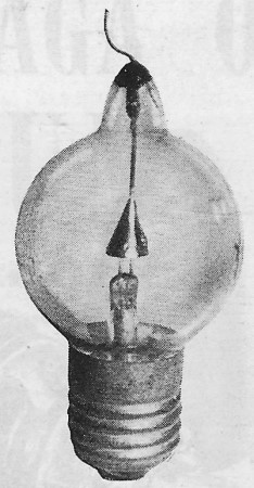
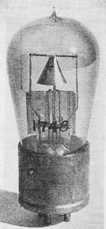
Fig. 164 - Small Kenotron with Edison medium screw base and conical anode. Used about 1917.
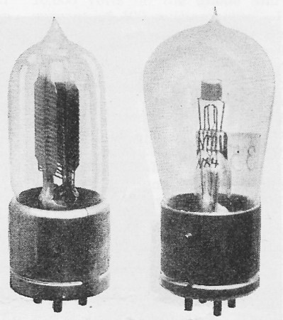
Fig. 165 - Small receiving type Pliotron with helical grid and filament and conical anode. Made about 1919. The "Type T" Pliotron was used as a low-power oscillator for small radio-telegraph and telephone sets, chiefly by the Navy on submarine chasers and in aircraft transmitters. The Type T was first designated by the Signal Corps as the "VT-12," and this tube is shown in Fig. 161. This designation was used but a short time when changes were made in the filament design to increase the life of the tube. The revised design was assigned the designation "VT-14" by the Signal Corps and "CG-1162" by the Navy. The bulb was similar to that used for the TB-1. The filament was a helix of 4.05 mil tungsten wire, with a total length of about 2 inches. It was supported by a molybdenum wire extending upward from the press. Concentric with the filament was a helical grid of 7 mil tungsten wire wound with an inside diameter of 0.130 inch and a pitch of 10 turns per inch. The length of the grid wire was about 3 3/8 inches, making a helix about 11/32 inch long. The anode was a cylinder of molybdenum 5 mils thick, with an inside diameter of 9/32 inch and a length of 5/8 inch. The filament normally consumed about 7.5 volts at a current of 1.75 amperes. The normal anode voltage was about 350 volts, and the anode current about 40 milliamperes. The power output when the tube was used as an oscillator was about 5 watts. It is interesting to note that many of these tubes were used by amateurs as Barkhausen oscillators in the earlier days of amateur activity at ultra-high frequencies, after they had appeared on the salvage market. The "Type U" Pliotron was the first of the General Electric "50-watters," and the prototype of the RCA UV-203. It was designated "CG-1144" by the Navy, and "VT-18" by the Signal Corps, and is shown in Fig. 162. It had a cylindrical bulb about 2 inches in diameter and 6 inches long. The filament consisted of a tungsten wire, 10.1 mils in diameter and having a total length of 3 7/8 inches. It was helical in shape, 1/8 inch inside diameter, with a pitch of 20 turns per inch. The filament was placed inside a grid helix and supported by a molybdenum rod passing up the axis of the helix. The grid was of 5 mil molybdenum wire helically wound on a 0.200 inch mandrel with a pitch of 20 turns per inch and a length of 7/8 inch. The grid was supported by two molybdenum wires electrically welded along the sides of the helix. The anode was of 5 mil sheet molybdenum bent in such a way as to form a cylinder 1/2 inch in diameter and 1 1.8 inches long, having four fins extending 3/8 inch out from it. These fins were intended to increase the radiating surface of the anode, thereby increasing the permissible anode dissipation. This tube operated with a filament current of 6.5 amperes at 10 volts. The normal anode voltage was 750-1000 and anode current 150-200 milliamperes. As a high-frequency oscillator this tube would put out about 50 watts. This tube was a later development than the other Pliotrons, but was used to a considerable extent by the Navy in seaplane transmitters. About 1200 were supplied to the Navy and 200 to the Army. The largest of the early Pliotrons was the "Type P," shown in Fig. 163. This was known to the Navy as the "CG-916" and to the Signal Corps as the "VT-10," and was the forerunner of the RCA UV-205. The bulb was about 5 inches in diameter. The filament was W-shaped, of 7 mil tungsten wire, with a total length of 6 1/4 inches. It operated with 3.6 amperes at a voltage of 13-19 volts. Surrounding the filament was a grid of 3 mil tungsten wirewound on a rectangular form of tungsten or molybdenum. The pitch of the grid was 30 turns per inch, and it was spaced 0.090 inch from the filament. The anode consisted of two rectangular plates of 25 mil thick tungsten. These were 2 by 2 3/8 inches in size, set parallel and 1/2 inch apart. The anode voltage was normally 1500-2000 volts and the anode current 150-200 milliamperes. As an oscillator it delivered about 250 watts, and was used by the Navy in seaplanes and flying boats. There were other tubes made in limited quantities during this period. One of these was the VT-16, which was being worked on at the time of the Armistice in 1918, and which differed only in minor details from the VT-14. Two other interesting tubes made by General Electric are shown in Figs. 164 and 165. That shown in Fig. 164 is a small Kenotron made in the General Electric Research Laboratory in 1916 or 1917. The cone-shaped anode, which is of molybdenum, fits closely around the filament in order to minimize the voltage drop in the tube. This tube was used to furnish high-voltage d.c. for some of the early experiments which led to broadcast transmitters. The Pliotron shown in Fig. 165 might almost be considered the first "variable mu" tube. The filament and grid were coaxial helices. The anode was conical, hence the ratio of grid-filament distance to plate-filament distance varied at different points along their common axis. This tube was made about 1919, but only on an experimental basis. To tube collectors who wish to identify the place of manufacture of specimens of these tubes, the following may be of interest. Many of these earlier General Electric tubes have hand written markings on the press, such as "H-6," "G-25," and the like. Those with the letter "H" were made at the Harrison Lamp Works and those marked "G" were made at Nela Park. The numbers following the letter designation are lot numbers. When the vacuum tubes made for the Armed Forces by the General Electric Company are compared with those made by the Western Electric Company one fact stands out in a startling manner. Tubes made by these two companies for identical purposes were totally different in appearance, materials, and structure, yet were interchangeable in use. As an illustration, let the reader compare the VT-11 described above with the VT-1 made by the Western Electric Company and described in a previous article. Both are shown in Fig. 166. No more forcible illustration could be made to bring out the point that each company brought to the field of development of this new device its own peculiar background of experience, gained through trying to solve its own problems in other fields. The scientists of these two companies, seeking answers to the same questions had, because of experience, taken different paths but arrived at a common designation.
Fig. 166 - Western Electric VT-1 (left). General Electric VT-11 (right). These tubes were interchangeable in use. Photograph courtesy Bell Telephone Laboratories. References 192. Langmuir, Irving - "The Effect of Space Charge and Residual Gases on Thermionic Currents in High Vacuum." Physical Review, 2nd Series, Vol. 2, 1913. pp. 450-486. See also Science Abstracts, A, No. 725, 1914. 193. Child C. D. - "Discharge from Hot Calcium Oxide." Physical Review. Vol. 32. No.5, May, 1911, pp. 492-511. 194. Lilienfeld, J. E. - "Die Elektrizitätsleitung im extremen Vakuum." Annalen der Physik, 4th Series, Vol. 32, No.9, 1910. pp. 673-738. 195. Langmuir, Irving - "Thermionenströme in hohen Vakuum." I. Wirkung der Raumladung." Physikalische Zeitschrift, Vol. 15, No.7, April, 1914, pp. 348·353. 196. Langmuir, Irving - "Thermionenströme in hohen Vakuum." II. Die Elelctronenemission seitens des Wolframs und die Wirkung von Gasresten." Phys. Zeit., Vol. 15. No, 10. May 15. 1914, pp. 516-526. 197. DlIshman, Saul - "A New Device for Rectifying High Tension Alternating Currents - The Kenotron." General Electric Review, Vol. 18. No.3, March, 1915, pp. 156-165. See also Physical Review, Vol. 5. April, 1915, p. 339. 198. Langmuir, Irving - "The Pure Electron. Discharge and Its Applications in Radio Telegraphy and Telephony." Proc. I. R, E., Vol. 3, 1915, pp. 261-293. 199. Hull, Albert W.-"Negative Resistance." Physical Review, 2nd Series, Vol. 7. No.1, January, 1916, pp. 141-143. Abstract of paper presented at meeting of American Physical Society in New York, October 30. 1915. 200. Hull, Albert W. - "The Dynatron - A Vacuum Tube Possessing Negative Resistance." Proc. I. R. E., Vol. 6. No. 1. February, 1918, pp. 5-35. 201. Hull, Albert W. - "The Effect of Uniform Magnetic Field on the Motion of Electrons between Coaxial Cylinders." Physical Review, 2nd. Series, Vol. 18. No.1, July, 1921, pp. 31-57. 202. Hull, Albert W. - "The Magnetron." Journal A. I. E. E., Vol. 40, September, 1921, pp. 715-723. (To be con't in January Issue) Robert Gillespie's Vacuum Tube Collection
Note: the entire series of "The Saga of Vacuum Tubes" articles can be accessed on the American Radio History website in PDF format. Below, I have take taken the time to list and link to each edition containing parts 1 through 22, along with the pages on which they begin.
Posted May 21, 2020 |
||