Saga of the Vacuum Tube
|
||
Saga of the Vacuum Tube, by Gerald F. J. Tyne Where else other than an original article like this one from a 1945 issue of Radio News magazine are you likely to find such detailed information on the construction of early vacuum tubes? This is Part 21 of the "Saga of the Tube" series. The reference list for information on various tubes is extensive. Having always been interested in the origin of names and designations of components of all sorts, things like learning "...the designation 'EVN' indicates that the tube was intended for use in a receiver (E = Empfanger) as an amplifier (V = Yerstärker ) at low frequencies (N = Niederfrequenz)" is appreciated. You will find many articles on the history of vacuum tubes, beginning with Dr. Lee de Forest's audion, by searching RF Cafe. I found the death notice of author Gerald F. J. Tyne in the April 4, 1981 edition of The New York Times newspaper - headline: "Gerald F. J. Tyne, 81, an Engineer, Researcher and Museum Director." Find-a-Grave. See list of all 22 parts at bottom of page. Part 21. Vacuum tube developments that were carried on in France and Germany during the first World War.
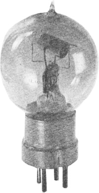
Fig. 223 - French Type "S" made by Fotos. Photograph courtesy Radio Corporation of America. By Gerald F. J. Tyne, Research Engineer, New York Vacuum tube development on the Continent during World War I was carried on chiefly in France and Germany, although the Dutch and Russians were also active. The work in France, as has previously been mentioned, was done almost entirely by the French Military Telegraphic Service under the able guidance of Colonel (later General) Ferrie. Early in the war, the French realized the manifold advantages of wireless telegraphy as a medium of communication in military work. Since military stations, of necessity, must be portable, the transmitters and receivers must be light weight, which necessitates a minimum of power consumption. The need for reliable communication under all conditions could be met by using high power transmitters and relatively low sensitivity receivers. Since the weight and bulk of transmitting equipment increases rapidly with the requirements for radiated power, this solution was not a satisfactory one. The use of low or medium power transmitters in conjunction with high sensitivity receivers was much more desirable, even necessary. To increase receiver sensitivity some form of amplifying device must be used. The three electrode vacuum tube was, by far, the best device available. In August, 1914, the French Military Telegraphic Service instituted an intensive development program with a view to obtaining a vacuum tube suitable for military applications. While development of a number of types was followed, problems of supply and distribution dictated the provision of a universal tube, one which could be used as high or low frequency amplifier, detector, or oscillator. The design of such a tube was settled upon early in the program and quantity production was undertaken in 1915-1916.301 It was a hard tube, known usually as the French tube, although it was also designated as the Type S tube. There were minor variations in construction, depending on the manufacturer.
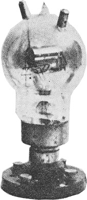
Fig. 224 - (left) French Kamerad type, in display socket. Photograph courtesy Bell Telephone Laboratories. Fig. 225 - (right) 50 watt transmitting tube of the Horned type. Photograph courtesy R. McV. Weston and Electric Communication.
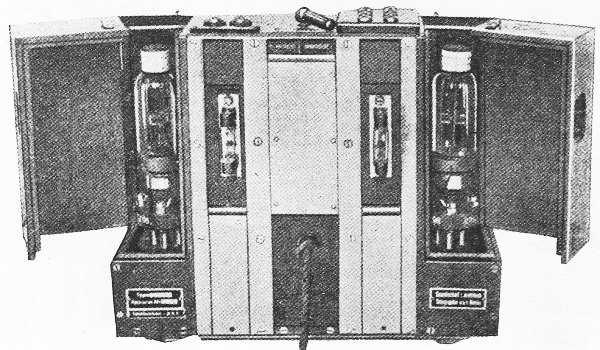
Fig. 226 - High-frequency amplifier using LRS Relay. Reproduced from "Handbuch der drahtlosen Telegraphie und Telephonie" by Eugen Nesper.
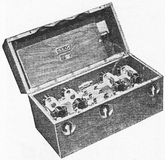
Fig. 227 - Close-up of LRS Relay used as a high frequency amplifier showing interior of apparatus. Photograph courtesy Clark Historical Library).
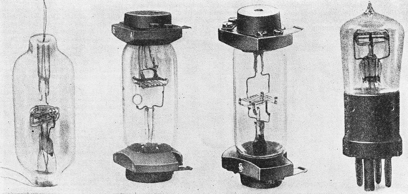
Fig. 228 - Development series of Siemens & Halske Type "A" Tube. Reproduced from "Veroffentlichungen aus dem Gebiete der Hachrichtentechnik" - 1935.
Fig. 229 - A.E.G. Type K4 Amplifier, showing use of type K3 tubes in last stages. Reproduced from Zenneck-Rukop "Lehrbuch der drahtlosen Telegraphie" - 1925.
Fig. 230 - Telefunken EVN89 Amplifier using EVN94 tubes. Reproduced from Zenmeck-Rukop "Lehrbuch der drahtlosen Telegraphie" - 1925.
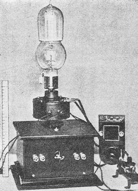
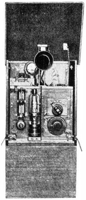
Fig. 231 - Telefunken transmitter made in 1915, using EVN129 tube. Reproduced from Zenneck-Rukop "Lehrbuch der drahtlosen Telegraphie" - 1925.
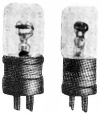
Fig. 232 - (left) EVN171 tube. Reproduced from Telefunken Festschrift - 1928. Fig. 233 - (right) EVE173 tube. Reproduced from Telefunken Festschrift - 1928. Fig. 224 shows one of these tubes. The element assembly was of the concentric cylindrical type, mounted with the axis of the assembly horizontal. The anode was a cylinder of sheet nickel, 0.59 inch long and 0.39 inch in diameter. The filament was of pure tungsten about 0.83 inch long and when operated at the normal voltage of 4 volts ran at a temperature of about 2400° K. The variations in construction of models, made by different manufacturers, were chiefly in the helical grid structure. In the Lampe Fotos, the grid was of 0.008 inch molybdenum wire, wound with a pitch of 0.051 Inch and of 12 turns, the total length being 0.63 inch. Its diameter was about 0.18. inch. In the Lampe Metal, the grid was of 0.011 inch diameter nickel wire wound with a pitch of 0.067 inch and had 11 turns, with a total length of 0.75 inch. The diameter of the helix was about 0.16 inch.302 The base was usually of sheet metal with a ceramic insert which carried the pins. The fastening arrangement for the pins was not a very secure one, and they frequently worked loose in the base. The bulb was about 2.2 inches in diameter. This tube was operated for receiving applications at its normal filament voltage of 4 volts, and filament current of 0.6 to 0.8 ampere. When used for transmitting purposes, the filament voltage was increased to 5 or 5.5 volts with consequent increase in output and reduction in operating life. The maximum permissible anode voltage, when used for transmitting, was 400 volts, while anode voltages of 15 to 50 were used in receiving. When attempts were made to utilize this tube in a multistage radio frequency amplifier, difficulties were encountered. The amplifiers used at that time were of the resistance-capacitance coupled type and the high input capacitance (15 μμfd.) of this tube limited its use to frequencies below about 600 kc. This upper limit was extended to about 1500 kc. by the use of a modification of this tube known to the French as the Lampe aux cornes, and to others as the horned valve or Kamerad valve.303 One of these tubes is shown in Fig. 223. The grid and anode are supported from wires which are embedded into projections on the press, and the electrical connections are brought to caps on the top of the bulb, separated by a considerable distance. This construction considerably reduced the tubes input capacitance. There were also a number of other and higher-powered tubes of this same general construction developed for military transmitter applications. One of these is the 50-watt output transmitting tube shown in Fig. 225. In Germany, the first attempts at the use of tubes for radio work were conducted with the von Lieben-Reisz-Strauss tube known as the LRS Relay, which was described in a preceding article. The LRS Relay was employed both as an oscillator and as a high-frequency amplifier in addition to its originally intended use, that of an audio-frequency amplifier. Fig. 226 shows the general arrangement for using this tube as a high-frequency amplifier and Fig. 227 shows a close-up of the assembly with some of the box covers removed. The first German high-vacuum tubes were developed shortly before the beginning of World War I and their refinement and improvement were greatly accelerated by military necessity. One of the first uses to which they were put was that of listening-in devices used to pick up enemy conversations. The first of these tubes, known as the Siemens & Halske Type A, is shown in Fig. 228 in its various stages of development.304 It followed, in general, the construction of the de Forest Audion and like it was a very inefficient device. Unlike its progenitor however, it was quite free from noise and microphonic action, chiefly because of its mechanical construction. The circular disk anode and spiral grid were held rigidly in place by means of glass spacers into which the elements were pressed. The bowed filament operated with 0.52 ampere at about 2.2 volts; the tube had an amplification factor of about 15 and an anode resistance of about 120,000 ohms. It had the advantage of taking a very small anode current, so that the anode batteries could be small and light. Fig. 228. While Fig. 228A shows the earliest stage of development, the tube as actually used in field equipment, even at this stage, was fitted with end mountings similar to those shown in Fig. 228B.305 Fig. 228B shows the second stage (attained in 1916) in the evolution of this tube. In it is shown the first step toward the punched grid which was finally used. The grid has been changed from spiral to zig-zag, still mounted in glass supports; the anode is rectangular to conform to the changed shape of the grid, and the filament has been changed to one parallel with the plane of the grid and equipped with a tensioning spring. The next step, shown in Fig. 228C, which was attained in 1917, utilizes a punched grid to replace the zig-zag wire. The final stage in this series is shown in Fig. 228D, in which the tube has been changed to single-ended construction with a single press, and a conventional 4-pin base employed. Another early type, made by A.E.G. (Allegemeine Elektricitats Gesellechajt ), followed more closely the design of the original de Forest Audion. It too was double-ended and had end fittings similar to the Siemens & Halske Type A. In the A.E.G. tube the hairpin shaped filament was surrounded by a zig-zag grid wound on formed glass arbors, and both filament and grid were supported from the bottom press. The anode was shaped like an inverted U, was supported from the upper press, and fitted rather closely over the filament-grid assembly. This tube was identified as the A.E.G. K3 tube, and was used in the final stages of the A.E.G. K4 Amplifier, shown in Fig. 229.306 The Telefunken laboratories, as distinguished from those of Siemens & Halske and A.E.G., had been working on high-vacuum tubes since about the middle of 1913 and by early 1914 had standardized on the use of the high-vacuum tube for radio reception.307 These tubes had a construction similar to the Siemens & Halske tube described above; that is, plane anode, spiral grid, and bowed filament, in this case of helically wound tungsten wire. The EVN129 was provided with metal plates on each side of the filament in order to prevent the emitted electrons from reaching the walls of the tube, to which they might be impelled by the magnetic field resulting from the filament current.308 The first application of the EVN94 was in the EV89 Amplifier shown in Fig. 230. This amplifier was first produced in July 1914.309 The EVN129 was originally developed for use as a heterodyne oscillator but was also used as a low-powered transmitting tube in sets of the type shown in Fig. 231, which were first made in June of 1915. The designation EVN indicates that the tube was intended for use in a receiver (E = Empfanger) as an amplifier (V = Yerstärker ) at low frequencies (N = Niederfrequenz).310 Another tube also intended for use in low-frequency amplifiers was the EVN171, shown in Fig. 232. This tube operated with a filament current of 0.5 to 0.55 ampere at 2.7 volts and used 80-100 volts on the anode. It had an amplification factor of about 10, a mutual conductance of about 100 micromhos, and an internal resistance of about 100,000 ohms.311 By 1914 the Telefunken engineers had decided to change over to a cylindrical element assembly and one of the first of the new type tubes, intended for use in the EVE211 Amplifier, was designated EVE173. This tube is shown in Fig. 233. It was intended to duplicate the characteristics of the EVN171 and, for a time, both tubes were made, eventually the EVN171 being abandoned. Like its predecessors, the earlier EVE173s used nickel in the anode and the grid. The grid was of thin nickel ribbon with a stiffening rib applied longitudinally. Later production of this tube, about 1918, influenced by the shortages of material which had developed in Germany by that time, had anodes of copper, and sometimes grids of copper as well. The copper used was chemically treated to eliminate surface impurities and make the tubes uniform in their operating characteristics. References 301. Ferrie, General - "Lemploi dez audions ou lampes a trois electrodes pendant la guerre." Revue Generale de l'Electricite, Vol. 6, No. 26, December 27, 1919; pp. 933-935. Fig. 231 302. Gutton, C - "La lampe-valve a trois electrodes." Revue Generale de l'Electricite, Vol. 5. April 26, 1919, pp. 629-640. See also Gutton's "La lampe a trois electrodes" Librairie Scientifiques Albert Blanchard - Paris - 1925, pp. 23-24. Fig. 232 Fig. 233 303. "Notice sur les lampes-valves a 3 electrodes et leurs applications" Ministere de la Guerre - Etablissement Central du Materiel de la Radiotelegraphie Militaire - April 1918. 304. Nebel, C. - "Die Entwicklung der Siemens Fernsprechrohre" Veroffentlichungen aus dem Gebiete der Nachrichtentechnik - 1935, Vol. 5, No. 4, pp. 215-226. 305. Stanley, Rupert - "Textbook of Wireless Telegraphy. Vol. II - Valves and Valve Apparatus" 2nd edition, Longmans Green - 1919, p. 182. 306. Zenneck, Jonathan and Rukop, Hans - "Lehrbuch der drahtlosen Telegraphie" 5th edition, 1925, Verlag von Ferdinand Enke - Stuttgart. p. 787. 307. Meissner, A. - "The development of tube transmitters by the Telefunken Company" Proceedings I.R.E., Vol. 10, February 1922, pp. 3-23. 308. See reference 307, p. 5. 309. Rukop, Hans - "25 Jahre Telefunken - Die Telefunkenrohren und ihre Geschichte" Telefunken Festschrift. 1928, p. 115. 310. See reference 309, p. 118. 311. Groskowski, J. - "Les lampes a plusieurs electrodes et leurs applications en radiotechnique" Etienne Chiron - Paris - 1925, p. 126. (To be continued)
Posted October 27, 2022 Robert Gillespie's Vacuum Tube Collection
Note: the entire series of "The Saga of Vacuum Tubes" articles can be accessed on the American Radio History website in PDF format. Below, I have take taken the time to list and link to each edition containing parts 1 through 22, along with the pages on which they begin.
|
||