How Television Tubes are Made
July 1938 Radio News

July 1938 Radio News
July 1938 Radio News Cover - RF Cafe[Table of Contents]

Wax nostalgic about and learn from the history of early electronics. See articles from Radio & Television News, published 1919-1959. All copyrights hereby acknowledged.

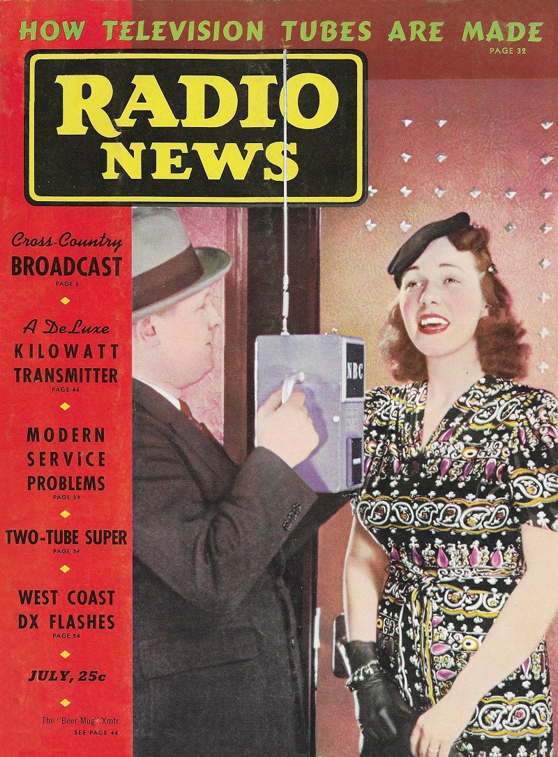
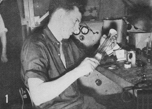
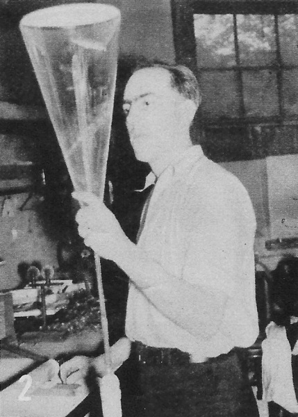
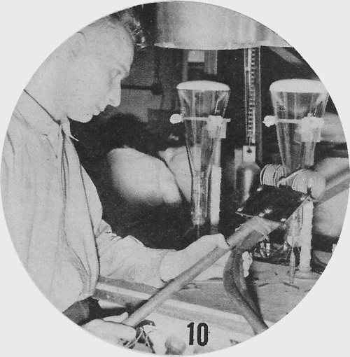
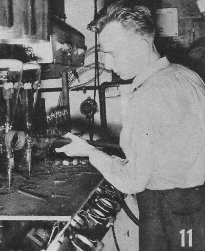
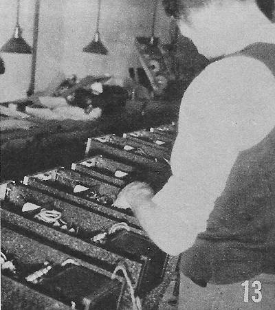
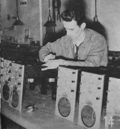
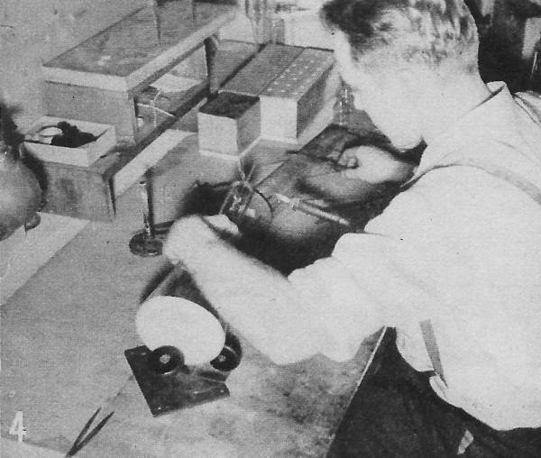
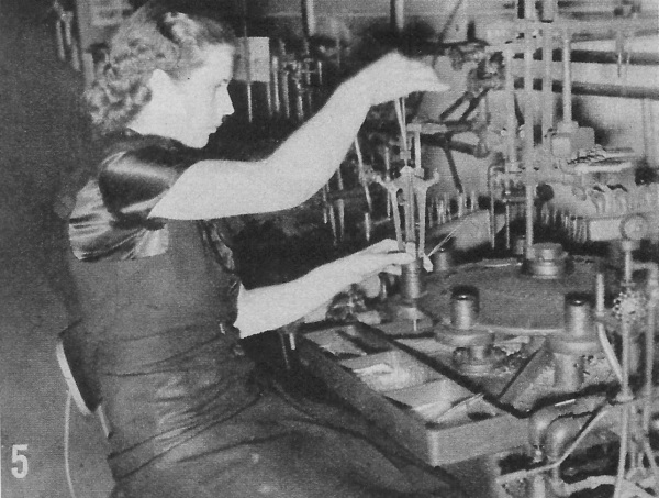
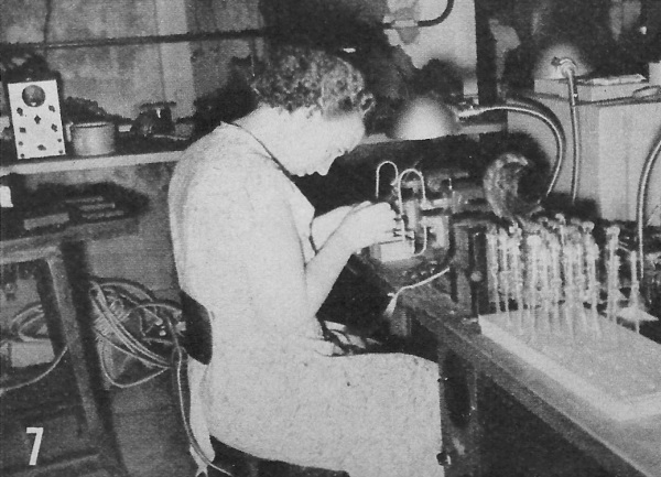
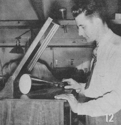
Even in the late 1930s when this article appeared in Radio News magazine, factory automation had made significant progress from the times when nearly every step of the process had to be performed by hand by workers. However, as components became smaller, more delicate, and precision assembly was essential to assure acceptable performance and reliability, direct human interaction was the only available means for getting the job done. As can be seen in this array of photos from the DuMont company's television cathode ray tube (CRT) production line, simple monochrome tubes required the precision and in-situ decision making of many kinds of skilled craftsmen (and craftswomen). Stories in later editions of various electronics magazines showed that although the level of automation had increased in the production of more complicated color CRTs, there was still a lot of manual labor involved (see list of TV articles below).

How Television Cathode Ray Tubes Are Made

Cathode Ray Tubes (CRTs) are almost universally used in the reception of television signals. How these complicated tubes are manufactured is clearly shown in the series of pictures below. At present the C.R. tubes are used in oscillographs.

Trimming screen of 2" TV CRT - RF Cafe

Trimming screen of 9" TV CRT  - RF Cafe

Trimming screen of 12" TV CRT  - RF Cafe

 Figs. 1, 2, 3 - Trimming screens of 2", 9", and 12" tubes. They must be evenly trimmed to insure a perfect picture. Tubes must stand tremendous pressure

Bombarding TV CRTs - RF Cafe

This heats elements of tube to white-hot temperature - RF Cafe

Released gases are drawn off by the mercury pump - RF Cafe

Figs. 9, 10,  11- Bombarding tubes. This heats elements of tube to white-hot temperature. Released gases are drawn off by the mercury pump.

Oscillographs on the production line - RF Cafe

Parts are wired in and components are properly mounted - RF Cafe

Figs. 13, 14 - Oscillographs on the production line. Here raw parts are wired in and components are properly mounted.

Stress in glass must be minimized or moved to center - RF Cafe

Fig. 4 -  Annealing tubes. Stress in glass must be minimized or moved to center out of danger zone. This process shortens and flares blank to prevent any chipping.

Wires are placed between jaws with glass collar - RF Cafe

Fig. 5 - Assembling stem mounts. Wires are placed between jaws with glass collar. Jaws revolve between flames which heat collar and "cement" it to wires forming stem mount.

The exhaust port of 2" tube is formed by a glass blower - RF Cafe

Fig. 6 - The exhaust port of 2" tube is formed by a glass blower. An ancient art for the most modern discovery.

Stem mounts being assembled prior to insertion in collars - RF Cafe

Essentials are spot-welded to insure complete rigidity - RF Cafe

Figs. 7, 8 - Stem mounts being assembled prior to insertion in collars. Essentials are spot-welded to insure complete rigidity. Frequent inspections assure early discovery of imperfections.

The finished tube is examined for stress and strain by means of a polariscope - RF Cafe

Fig. 12 - The finished tube is examined for stress and strain by means of a polariscope. Variegated hues reflected indicate strain is present.

Testing the action of the completed oscillograph - RF Cafe

Fig. 15 - Testing the action of the completed oscillograph. Long tests are necessary to insure against breakdown in use. Accuracy is essential and tubes are so designed to give this result. Time studies are made to determine deterioration.

Allen B. DuMont examines a 12 in. Cathode Ray tube - RF Cafe

Fig. 16 - Allen B. DuMont examines a 12 in. Cathode Ray tube. This is one of the largest manufactured. They must be gingerly handled because of the constant danger of an implosion (the opposite of "explosion"). With careful construction and the shifting of the stresses to the center of the tube (See picture No.4), this occurrence is minimized. The source of the implosion is the external air pressure of 15 lbs. to the square inch to which the tube is constantly subjected. Without the outside air pressure, C.R. tubes could be built to any size and the picture projected could be as large as the ordinary movie.

Color and Monochrome (B&W) Television Articles


Posted January 4, 2022