The Spook - Another Weird Effect to Haunt TV |
||
How often have we all mistaken "spooks" for Barkhausen oscillations? Yeah, it's embarrassing, but we've all done it. I can't tell you how many times as a kid I saw the tell-tale effects on our old black and white TV and said, "Mom, can you remind Dad to do something about those dang Barkhausen oscillations when he gets home from the newspaper office?" If you believe that line of bull hockey, I've got some waterfront property in the Sahara Desert to sell you. The only thing close to "Barkhausen" I might have known back then was the name of a German beer house on Hogan's Heroes (for which I own the entire DVD set). Anyway, this article, written in the days of over-the-air television broadcasts, presents a solution to the annoying "spook" effect caused by poor oscillator circuit shielding. It is a propos for posting on October 31st (Halloween). The Spook - Another Weird Effect to Haunt TV
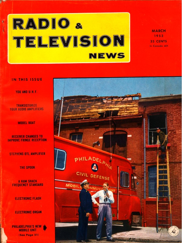
Fig. 1 - Hand-made r.f. chokes used for minimizing spook problem. By M. B. Knight Tube Department, Radio Corporation of America A simple solution to the problem of electromagnetic radiation from. horizontal deflection circuits of set. A number of interesting phenomena, sometimes not anticipated in fundamental studies, have cropped up in the electronic art. These phenomena often are identified by colorful names which are intriguing in themselves. The "spook," an interference effect in television receivers, may be destined to take its place in the language of the trade with such terms as "ghost," "barks," "motorboat," "birdies," "snow," and "jitter." Description of Spook The spook originates as electromagnetic radiation from the horizontal deflection circuits of television receivers and is picked up by the sensitive r.f. or i.f. circuits of the receivers. Like any other signal in the r.f. or i.f. circuits, the spook signal is amplified, detected, and applied to the grid or cathode circuit of the kinescope. When seen in the picture, it appears as a narrow vertical band very close to the left-hand edge of the raster and resembles the more familiar interference from Barkhausen oscillations in the horizontal-output tube. If the television signal is weak compared to the spook signal, the line is black and has ragged edges as shown in Fig. 2. If the television signal is of normal strength, the line is not black but has within its margins crawling diagonal lines which are caused by heterodyning between the television signal and the spook signal. The appearance of the spook when the television signal is of normal strength is shown in Fig. 3. Despite the similarity to Barkhausen oscillation, several distinguishing features establish the spook as a separate effect: (1) The line is always in the same place in the raster, very near the left-hand edge. (2) The interference, if picked up in the r.f. circuits, is always strongest on the lower-frequency channels, whereas Barkhausen may be more pronounced on either the low or high-frequency channels. (3) Experiments show that the radiation does not come from the horizontal-output tube, nor do the usual cures for Barkhausen oscillation, such as magnets, have any effect on it. Actually, the spook seldom has a serious degrading effect upon receiver performance. Because of its location on the raster, it is usually within the blanking period and it is almost always off the kinescope screen because receivers are normally adjusted to have a good margin of deflection width. The more common degrading influence of the spook is that it upsets the receiver synchronizing circuits. Because of the action of the detector circuit, the spook shows up in the video circuits as a pulse in the "black" direction, similar to the sync pulses. If it is of sufficient amplitude, the spook pulse will pass through the sync amplifier along with the regular sync pulses and may impair the operation of the horizontal a.f.c. circuits. Occasionally, two receivers are close enough together so that one picks up the spook interference from the other. The resulting picture disturbance is quite objectionable; if the receivers are tuned to different stations (the line-scanning frequencies of which may differ slightly), the spook line may move back and forth across the picture. Discovery of Spook
Fig. 2 - Appearance of "spook" interference with weak signal.
Fig. 3 - "Spook" interference with signal of normal strength. To the best of our knowledge, the spook phenomenon passed unnoticed, or at least uncommented upon, for three or four years of commercial receiver production. There are several reasons for this delay. First, because of the usual practice of scanning beyond the kinescope mask, the spook line is rarely seen. Second, because the intensity of the spook radiation is a function of the deflection power, it has become more evident as larger kinescopes, having larger deflection angles and accelerating voltages, have come into popular use. Third, the older deflection circuits were susceptible to Barkhausen oscillations, and the spook, even if observed, could easily be dismissed as Barkhausen. The advent of modern high-efficiency deflection circuits, however, called attention to the spook as a unique effect. The writer's first encounter with the spook occurred about two years ago during the development of the RCA- 223T1 horizontal-deflection transformer. The narrow vertical band appeared to be due to Barkhausen oscillation; further investigation, however, showed that cause to be unlikely because careful measurements established that the plate voltage of the horizontal-output tube was not negative at any time during the scanning cycle. Other engineers observed the effect at about the same time and established that it was not Barkhausen. No parasitic oscillation could be found and the mysterious nature of the effect caused it to be dubbed the "spook." The name seemed apt and has persisted. The effect was distressing to receiver designers, mainly because of its elusive nature, and efforts were made by the writer to locate the cause. After some investigation, a reasonable explanation was found, and methods of minimizing the interference were easily devised. How Spook Is Generated In the investigation of the nature and cause of the spook, a separate television receiver was used to search for the most prominent source of radiation. Although some radiation could be detected from most parts of the deflection circuit, the damper tube and its leads produced the strongest radiation. Scrutiny of the current waveforms in the horizontal deflection circuit showed that the spook line appears at the same instant that the damper tube begins conduction, approximately one microsecond after the completion of retrace. The damper tube plate current rises from zero to its maximum value of 350 to 400 milliamperes very rapidly. The rise time of the current was not measured precisely, but avail-\able equipment indicated that it was 0.1 microsecond or less. At any rate, it was apparent that the electromagnetic fields associated with such a rapid change of current and voltage must contain many high-frequency harmonics. It could be expected, therefore, that the high-frequency harmonics could be radiated to the signal circuits of the receiver. This theory was checked by exploring the radiation spectrum with a communications receiver. The receiver was tuned from about 300 kilocycles to 18 megacycles and a signal was detected at every harmonic of 15,750 cycles. A more significant observation was that no other signal was detected. The intensity of the harmonics diminished steadily as the receiver was tuned to higher frequencies. In addition, spook interference was found to be most severe on television Channel 2 and was successively less severe on higher-frequency channels. If the harmonics were being radiated as a result of the rapid plate-current change in the damper tube, it would be assumed that high-frequency harmonics would be of less amplitude than low-frequency harmonics. Small r.f. chokes were placed in the leads to the damper tube at the socket and the radiation was reduced considerably. The residual radiation came almost entirely from the internal structure of the tube itself. Further tests confirmed that the interference originated with the rapid change in the damper-tube plate current. Minimizing Spook Interference The rapid rise of plate current in the damper tube is inherent in the proper operation of deflection circuits. Practical means for slowing down the increase in current are not at hand, and it is not expected, therefore, that the spook can be eliminated entirely. It is possible, however, to reduce considerably the detrimental effects. One approach to the problem of reducing spook interference is to minimize the susceptibility of the r.f. and i.f. circuits to the radiation by physically separating the r.f. and Lf. circuits from the deflection circuits. This separation is chiefly a chassis design problem; good chassis layout in this respect is normal in commercial receivers. The technician is more concerned with the installation of the receiver; he should be sure that the antenna lead-in is dressed away from the deflection circuits. Not much can be done along this line if an in-cabinet antenna is used. A second approach to this problem is to minimize the radiation from the deflection circuits. Because the damper tube and its leads can be thought of as a transmitting antenna which radiates the spook, a logical approach is to make the transmitting antenna as small as possible and to provide a shield between this "antenna" and the receiver r.f. and i.f. circuits. It was mentioned before that insertion of r.f. chokes in the leads to the damper tube limited the "antenna" to the tube structure itself. The value of the chokes is not critical, but must be large enough to be effective in the television band without being so large that ringing is caused in the deflection circuit. Chokes having inductance values between 1 microhenry and 5 microhenrys are suitable and are available commercially. Chokes for the plate and cathode circuits can be made by winding approximately 30 turns of AWG #28 enamel or Formex wire on a one-watt resistor. Ordinarily, it is not important to insert chokes in the heater circuit. If heater chokes are used, however, wire at least as large as AWG #20 should be used to carry the heater current. The stiffness of this size wire makes a coil form unnecessary; a coil of approximately 20 turns about 3/8 inch in diameter is adequate. Fig. 1 illustrates typical hand-made chokes. After chokes have been placed in the damper tube leads, it is desirable to shield the tube from the receiver r.f. and i.f. circuits. The high-voltage enclosures used in most receivers provide adequate shielding. The shield should be inspected to see that it is grounded at as many points as possible. If there are any large holes in the enclosure, they may be covered with ordinary copper wire screen to improve the effectiveness of the shield. Capacitive coupling between the damper tube and any leads which come out of the high-voltage enclosure should be minimized by careful lead dress. A close-fitting shield around the tube, however, is neither necessary nor desirable because of the resultant increase in bulb temperature. In the commercially popular auto-transformer and direct-drive types of deflection circuits, experience has indicated that spook interference can be greatly reduced by the addition of only one r.f. choke. In such circuits, most of the radiation usually comes from the "B+" lead which is connected to the plate of the damper tube. (The cathode lead is quite well shielded by the high-voltage enclosure.) The r.f. choke, therefore, should be placed in the plate lead of the damper tube at the socket. The addition of a condenser of approximately 100 μμfd. between the chassis and the "B+" side of the choke may give further improvement. The techniques suggested for reducing spook interference are not all-inclusive. Each type of deflection circuit and each mechanical layout requires individual attention. It is expected, however, that an understanding of the source of the interference will be of help to the troubleshooter when spook problems appear.
Posted October 31, 2022 |
||