Developments in Solid Dielectric R.F. Transmission Lines |
|
One of the many advances in radio technology during World War II - transmission lines - is reported on here in a 1952 issue of Radio & Television News magazine. If you are less than maybe 30 years old there is a good chance the only kind of RF transmission line you have ever been exposed to is coaxial cable. I say 30 years old because by the early 1990s the majority of homes had either cable TV service or rooftop TV antenna lead-ins were using 75 Ω coaxial cable rather than the traditional 300 Ω twin lead (with the assistance of an impedance transformer at the antenna end). Author R.C. Graham rightly credits an efficient method of high-volume commercial polyethylene for use as a dielectric both for twin lead and coaxial cable. Prior to that some compound of rubber or steatite (had not heard of it, aka soapstone) was commonly used. If you are researching the history of RF transmission lines, this article will be a valuable collection of information. Developments in Solid Dielectric R.F. Transmission Lines
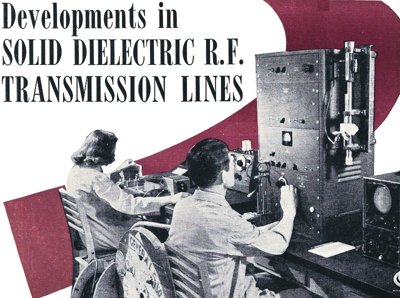
Fig. 1 - Testing high-frequency cables at the General Cable Corporation plant. By R. C. Graham, W8LUQ Chief Engr. Thermionic Engineering Corp. Practical graphs and tables of transmission lines for use in conventional amateur rigs. Prewar installations of transmission lines or "feeder" systems generally consisted of open wire or air spaced coaxial constructions. It is true that solid insulated lines were making headway due to improvements in dielectrics and designs but the appreciable differences in transmission efficiency favored air spaced lines. Insulated lines (coaxial and especially twisted pair) were used in many instances where compactness, mechanical, or some particular feature was more important than attenuation characteristics - a good example being the small twisted pair designs used for connection to doublet type receiving antennas. The advantages of a good insulated line are numerous and may be summarized as follows; appearance, compactness, ease of installation, flexibility, reduced line radiation, low impedance, single coupling devices and "matching" networks, and safety. If the transmission efficiency could be made to approach that of air spaced lines and if the effects of weather were eliminated it would appear that solid insulated lines would then be preferred for most installations. It is, therefore, gratifying to describe some important wartime developments that now make it possible to meet these exacting conditions. In this connection, an outstanding contribution was the development of a new and remarkable insulation or dielectric called Polyethylene.
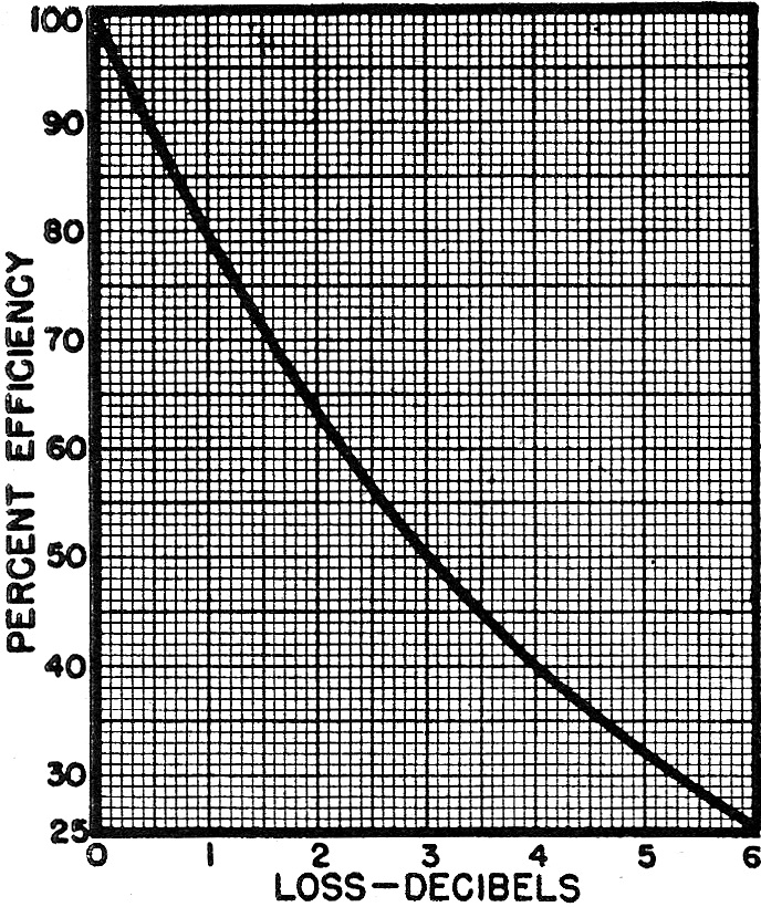
Fig. 2 - Line attenuation in decibels. Polyethylene* Polyethylene, an original British discovery, is a synthetic plastic material which may be chemically described as a pure hydrocarbon resin produced by the high pressure polymerization of ethylene gas. The story of how this difficult process was adapted to large scale wartime production is a subject in itself - another excellent example of American technical achievement. Polyethylene is an odorless, waxy, flexible material that is now available in a variety of colors. Electrically, it is the best material yet developed for extruded insulation and a similarity to Polystyrene is revealed by the characteristics shown in Table 1 as compared with conventional rubber and steatite insulation. Physically, the material possesses remarkable toughness and at normal temperatures is resistant to oils, acids, alkalies, and most chemicals. In addition to a high degree of weather resistance, Polyethylene is usable at temperatures from far below zero to as high as 185° Fahrenheit. One of its most useful characteristics is its outstanding resistance to water - being greatly superior to any other non-metallic wire covering in this respect. For most practical purposes Polyethylene may be accepted as water-repellent. At present, this material may be considered as moderate in cost as compared to other plastics) but increased demand and production should make Polyethylene one of chemistry's cheapest plastics. Types and Design of Cable
Table 1 - Characteristics of polyethylene as compared to low-loss rubber and steatite.
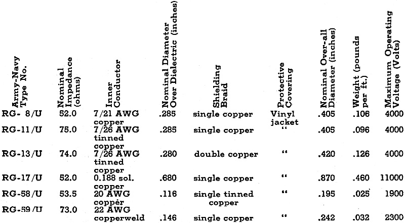
Table 2 - Summary of the characteristics of the more popular polyethylene cables. The design of high frequency cables not only involves electrical parameters but must include such physical and mechanical considerations as flexibility, size, handling, weathering, termination, and the most practical aspects of economy and manufacture. There are several different constructions that are used for solid insulated high frequency transmission cables. These may be described as follows: Coaxial - This is becoming the most popular type of insulated line and generally consists of a Polyethylene insulated center wire with an over-all tight fitting concentric metallic covering - such as a flexible copper wire braid. Further mechanical coverings such as jackets or braids mayor may not be included for specific service conditions. A single coaxial cable by itself forms an "unbalanced" line and is generally operated as an untuned line. It is not feasible to manufacture such cables except in an impedance range of 12 to 85 ohms. Attenuation or efficiency is largely dependent upon physical size (amount of copper and insulation). For example, some large coaxial cables with losses as low as 0.2 db. per 100 ft. at 14 megacycles have been manufactured although types recommended for most amateur installations average about 0.6 db. per 100 ft. Power rating is also dependent upon size and the two cables referred to above may be safely rated (14 mc.) at 30 kw. and 3, kw. respectively. Because of shielding, a coaxial cable has a high degree of operational stability - that is, properties are not affected by weather or installation conditions. Dual Coaxial - As the name implies this arrangement merely consists of two identical and adjacent single coaxial cables in which the two concentric or coaxial conductors are electrically connected - either within the cable or externally. When operated as a "balanced" line the two conductors are connected in series and the impedance is twice that of the single coaxial circuit. When operated as an "unbalanced" line the center conductors are connected in parallel and one half the impedance of the single coaxial circuit is obtained. In either case the attenuation loss is the same and equal to the loss of the single coaxial circuit. Thus, three different impedance values with equal loss could be obtained from the dual coaxial circuit. For example, two 70 ohm coaxial circuits could be utilized in anyone of the following methods: single circuit 70 ohms parallel circuit 35 ohms series circuit 140 ohms Shielded Twin - This is similar to the dual coaxial arrangement except the two insulated conductors (not coaxial) are covered by a single electrical metallic shield. It is recommended that this design be used for "balanced" or series connected loads. CONDUCTOR
Fig. 3 - End views of several conventional type high-frequency cables.
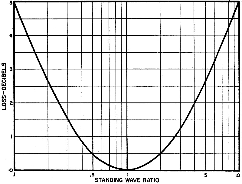
Fig. 4 - Graph indicates the db. loss due to different standing wave ratios.
Fig. 5 - Transmission losses for several well-known types of lines. Twisted Pair - This assembly has been well known as an economical feeder for doublet antennas. It consists of two insulated conductors twisted together as a "balanced" un-tuned line. Since shielding is not used the line impedance and mutual capacitance are subject to variations due to presence of water or external grounds. By proper design, line impedances from 50 to 150 ohms are feasible as well as attenuation values corresponding to equivalent conductor coaxial cables. Twin - This recent low cost design consists of two parallel insulated conductors with a relatively wide spacing between centers. It is mainly useful as a "balanced" medium to high impedance line with practicable values from 150 to 400 ohms. Because of its low mutual capacitance the attenuation losses are relatively low. Being unshielded this line is subject to slight impedance variations with weather and installation conditions but is not nearly so affected in this respect as the twisted pair. However, the lack of the closer spacing and transportation of the pair may result in a greater magnitude of line radiation or pickup. The twin line may be operated as a tuned line (as well as untuned) Whereas the twisted pair should not be. Mathematical formulas relating to design properties of these cables (impedance, attenuation, velocity of propagation, capacitance, etc.) can be found ill the textbooks. Dielectric constant arid power factor of the insulation plus the geometry and dimensions of the cable are the main factors involved in the electrical design solutions. The final test is to judge whether or not these design methods and subsequent manufacture have been correct. Equipment used for this testing is illustrated in Fig. 1. Line Efficiency Just what is meant by the expression of line attenuation in decibels? This is merely an accurate mathematical description of the line efficiency - or in other words, the ratio of output in input power. Fig. 2 is a graphical presentation of decibels expressed as per-cent efficiency. For example, a total line loss of 1.0 db. represents 79.4 per-cent efficiency, (from Fig. 2) which means that for every 100 watts put into the line at the transmitter end a value of 79.4 watts is obtained at the antenna end. In this same connection there may be other effects contributing to the total loss in addition to that supplied by the untuned transmission line - such as that loss due to the mismatching of impedances. When the line impedance differs from the antenna impedance a standing wave ratio equal to the ratio of these impedances is established. For example, a 35 ohm line connected to a 70 ohm antenna section has a standing wave ratio of 2 (70/35) or. 0.5 (35170). Fig. 4 indicates the db. loss due to different standing wave ratios. It is significant that impedance mismatches up to ratios of 2 to 1 cause almost negligible loss. This means that losses due to use of a 50 ohm cable to a 70 ohm load (and vice versa) are not of any serious consequence. Such mismatch may, of course, have some effect on coupling and cause a slight increase in line radiation. Available Cable Types Polyethylene insulated high frequency cables were produced in large volume for wartime radio and radar uses. The Army and Navy standardized on certain designs for specific applications and assigned a type designation (RG series) to each. Since many of these same designs will have valuable features for peacetime radio use a brief summary of the more popular Polyethylene cables is given in Table 2. Fig. 5 illustrates the transmission loss for several well known types of lines. The improvement over rubber insulated designs can be recognized and it is further significant that the efficiency of a solid insulated line is now of the same magnitude as certain air-spaced types. Fig. 6 gives the power rating of some standard RG cables and indicates complete safety factors for all amateur services. It is in this particular characteristic that the Polyethylene insulated coaxial cables far excel the air-spaced coaxial lines. It is believed that RG-8/U, RG-11/U, RG-13/U, RG-17/U and RG-59/U will be the most popular and practical Army-Navy types for amateur applications. In addition to these, other new types (coaxial, dual coaxial, twisted pair, and twin) designed for specific applications will be available. These flexible cables are adaptable to any method of installation. They may be suspended in air, buried in the ground, or fastened to any convenient support without hazardous or operational effects.
Table 3 - Suggested methods of feeding some of the more common types of antennas.
Fig. 6 - Graph indicates power rating of several standard RG cables. Power rating is based on center conductor temperature of 175 degrees Fahrenheit, and an ambient temperature of 104 degrees Fahrenheit. Splices should be avoided due to impedance variations. When necessary, a conventional conductor splice may be wrapped with sufficient rubber insulating tape with a protective layer and the shield joined by connecting a wire to each side of the joint. Manually prepared terminals are satisfactory; the preferred procedure is to remove all coverings and shields about 4 inches from the end and permit the Polyethylene insulation to remain intact to the end. The value of 4" should be increased to about 12" for outside or exposed connections. Protective tapes or paints are not recommended or needed at terminals. A series of standard male and female shielded connectors are available for the Army-Navy type cables. A description of these devices may be obtained from any of the several connector manufacturers. In connecting a shielded or coaxial cable to the antenna it is advisable to provide a good ground connection to the shield at the transmitter (or receiver) end. No additional ground connections are required. If a dual coaxial arrangement is used it is recommended that the two cables be maintained as physically close together as possible and that frequent electrical bonds of the two shields be made. It should be remembered that Polyethylene is thermoplastic and may soften and deform under excessive heat. Therefore, careful soldering technique is advisable. When used as untuned lines these cables may. be used in any desired length-the efficiency of which may be determined from Figs. 2 and 5. For example, let us assume we wish to maintain at least a 750/0 line efficiency at 28 megacycles. Fig. 2 indicates that the total line loss must not exceed 1.25 decibels for this condition. Reference to the 28 me. loss given in Fig. 5 and subsequent multiplication." then shows that we could use any length up to 350 ft. of RG-17/U, 130 ft. of RG-13/U or RG-ll/U or 300 ohm twin, or 120 ft. of RG-8/U. Coupling of the untuned line to the transmitter is conventional in that link or impedance network devices are satisfactory. When used as tuned lines it must be observed that the velocity of propagation along Polyethylene insulated coaxial lines is about 67 per-cent of that of free space (air). Consequently, a half-wave in electrical length is 67 per-cent of that determined for an open wire line. The formula, length of half-wave, feet = 468 X 0.67/ƒmc, is reasonably exact. For the twin line this formula becomes 468 X 0.85/ƒmc. It would be impossible to cover all of the different methods of solid dielectric line arrangements that could be used for each of the many types of antennas. However, some of the more common antennas are listed in Table 3 together with some suggested methods of feeding. The use of these lines to feed close-spaced arrays is also possible as can be determined by analysis of the following relationship: Z0 = √(Z1Z2) Z0 = impedance of quarter wave matching section Z1 = antenna impedance Z2 = line impedance For a 3-element, close-spaced parasitically excited array Z1 is equal to 9 ohms. If a quarter wave matching section of Z0 equal to 35 ohms (parallel dual connection of RG-11/U, RG-13/U or RG59/U) is used it will then be possible to connect an untuned line (Z2 = 140 ohms) of a series dual arrangement of the same cables to the transmitter. * Polyethylene, a chemical name, is used by the Union Carbide and Carbon Corp. to identify its product. Polythene is the trade name used by the E. I. du Pont de Nemours Corp. to identify its product.
Posted March 22, 2022 |
|