Radio-Radar-Sonar in Naval Applications |
||
World War II was the "necessity" that elicited the "mother of invention" activity responsible for many huge leaps in technology - not the least of which was electronic verbal and non-verbal communications. By 1951, when this Radio & Television News magazine article on the sate of the art of military electronics was published, the United States was already in the midst of another war - this time in Korea - fighting back the frontiers of Communism and despotism. Along with radio and radar, Loran had become a major means of ocean and air navigation. A fair description of the operational details, including timing diagrams, is included in the text. Loran-A, the original system as it came to be known, was fully decommissioned in 1980, thereafter supplanted by Loran-C. With the advent of GPS, Galileo, and Glonass navigation systems and their low equipment and installation costs, Loran-C was eventually no longer needed either, causing it to be decommissioned in the U.S. in 2010.Norway's Loran-C stations, the last operational stations, were scheduled to close in 2016. In case you are wondering, this is a Veeder counter. Radio-Radar-Sonar in Naval Applications
Fig. 1 - A radar-equipped PT boat. By Samuel Freedman Technical Products and Services Co., Santee, California Radio-electronics plays a vital role in all naval operations. Vast laboratories work night and day to keep the U. S. Navy ahead in such developments. A discussion of radio, radar, and sonar equipment in naval . applications must, of necessity, be confined to declassified information at this time. Nevertheless, naval electronics today embraces all phases of radio and its offshoots, as developed during the past half century. It is used extensively on land, on the sea, under the surface of the sea, and in the air. It includes infrared, guided missiles, and atomic developments. It covers the entire frequency spectrum from very high powered, very low frequency stations (below 20 kc.) through the various frequency bands used for radiotelegraphy, radioteletype, radiotelephony, facsimile, and television. It extends to the microwave region for radar and communications. It continues still further to infrared or invisible light and even to the radioactive band of the electromagnetic spectrum where frequencies may be as high as 100 trillion megacycles or more - regions where electromagnetic waves are also known as rays or particles. Although many of these naval applications are paralleled or even exceeded by the Army and the Air Force, the use of electronics extends into the activities of the Bureau of Ships, Bureau of Aeronautics, Bureau of Ordnance, training activities of the Bureau of Personnel, and, on a small but expanding scale, into the activities of the Bureau of Medicine and Surgery. The Navy today has many major multi-million dollar laboratories and test centers which are wholly or primarily concerned with electronics. Their work overlaps only because electronics affects every phase of naval operations in such a way that so far it has been impractical to establish a single "Bureau of Electronics." These major laboratories and test centers include such installations as: The David Taylor Model Basin near Washington, D. C.; The Naval Research Laboratory of the Office of Naval Research in Anacostia, D. C. and its annex on Chesapeake Bay; The Naval Ordnance Laboratory in White Oak, Maryland, for the Bureau of Ordnance; The Special Devices Laboratory of the Office of Naval Research at Sands Point, Long Island; The Underwater Sound Laboratory of the Bureau of Ships and the Office of Naval Research at New London, Connecticut. The Naval Air Development Station at Johnsville, Pennsylvania; The Naval Air Test Center at Patuxent, Maryland; The Naval Air Missile Test Center at Point Mugu, California; The Naval Ordnance Test Station at Inyokern, California; and The Navy Electronics Laboratory of the Bureau of Ships at San Diego, California. The staffs of these laboratories, which are made up of both naval and civil service personnel, range from a few hundred to several thousand employees. In addition, this force is backed up by other activities in common with other defense services and the large laboratories of the National Advisory Committee on Aeronautics, such as the Ames Aeronautical Laboratory at Moffett Field, California. Their work is further reinforced by contracts and subcontracts for research, development, and production which are awarded to various industrial firms, universities, and laboratories in the United States. University contracts may cover strictly naval research problems or may be awarded in conjunction with the parallel requirements and interests of the other defense services. This research program also reaches into such activities as those of the Radio Technical Committee for Aeronautics, the Air Navigation Development Board, the Research and Development Board, and the Radio Technical Committee for the Marine Services, etc., all of which are primarily civilian in nature. Although the United States is singularly blessed in having a vast production potential, the Armed Services have not left their development programs to chance. Hundreds of millions of dollars have been spent in the past five years on research, development, and the production of prototypes. Those who were familiar with the Navy electronics organization during World War II will find that the Navy's dominant electronics organization, the Bureau of Ships, has continued to operate more or less intact although with a skeleton force. There have been practically no changes in the code organization setup other than those necessary to take care of new developments. The Bureaus of Aeronautics and Ordnance have likewise developed programs to take care of the electronics requirements of their particular branches. The small wartime Office of Patents and Inventions and the subsequent Office of Research and Inventions has been greatly expanded and is currently operating under the designation of the Office of Naval Research with a fine field laboratory of its own. Electronics, originally confined to naval communications apparatus, has now grown until it reaches into every phase of naval activity. In addition to its communications uses, electronics now serves in the fields of navigation and ordnance. The advent of radar on naval vessels, including several different types which perform specialized tasks, has skyrocketed the number of electron tubes in operation aboard such craft. This same condition also applies to aircraft and submarines. During World War II, the average submarine carried equipment using considerably more than 500 electronic tubes, but today that number has been increased and the range of the craft has been expanded as a result of improved and increased radio, radar, and sonar equipment aboard such vessels. Fig. 1 is an example of the use of radar equipment aboard even the smallest naval craft. Visible on top of the mast is the "thinking cap" of the PT boat. This so-called "Radome" bulb houses the antenna of the radar set aboard the vessel. Radar has proven invaluable to the hard-hitting PT boat because they operate chiefly under the cover of darkness. Under such conditions, radar's electronic eye pierces this Stygian gloom for a horizon and indicates targets as to direction and distance, in addition to providing warning of navigational hazards. When a PT boat operates against a large enemy vessel, it enjoys the advantage in that the larger ship yields a much stronger indication on the PT's radar screen and for a greater distance than the PT registers on the larger ship's screens. The PT because of its smaller dimensions and because it is fabricated of wood has poorer reflective properties and is, therefore, harder to pick up on the radar screen of the enemy vessel.
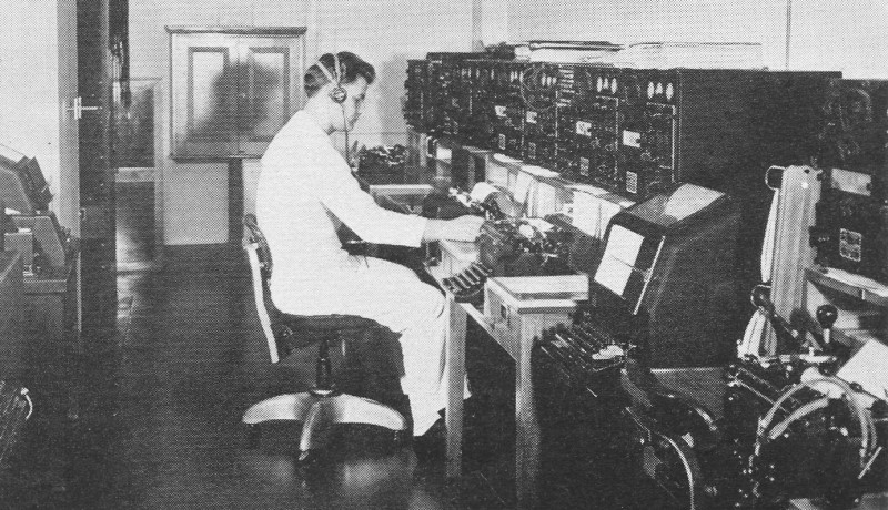
Fig. 2 - A naval communication room at the Cheltenham, Maryland, Naval Radio Station. In this installation both manual equipment and the newer radioteletype units are used.
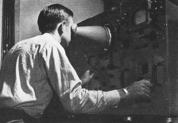
Fig. 3 - Radar equipment in operation at the Naval Research Lab.
Fig. 4 - Loran receiver indicator aboard a Coast Guard vessel. Many devices, usually considered as "land-based," have now been adapted to aircraft and seagoing uses. One such unit is the radioteletype. Fig, 2 shows a battery of radio apparatus and the radio teletypes used in naval communications. The Navy has adapted teletype to radio operation and has produced a workable combination which eliminates the need for an operator to decode a series of dots and dashes. The unit is an ordinary teletype which is connected by means of a converter to the radio transmitting and receiving apparatus. When receiving, the converter changes radio impulses into electrical energy which actuates the teletype. The transmitting process is identical. The unit has a gross speed of 60 words-per-minute as compared with 25 words-per-minute for fast radiotelegraphy. Radioteletype was first used under combat conditions during World War II at Iwo Jima and later proved itself at Okinawa and during the air strikes against the Japanese mainland. It is widely used now and, for example, when the President of the United States travels on a naval vessel, radio teletype is used to maintain constant contact with his office in Washington. Fig. 3 shows one of the many types of radar installations likely to be encountered on naval vessels. More compact versions have been developed for use on submarines and in aircraft. Developed independently by American, British, French, and German scientists during the decade preceding World War II, the refinement of radar equipment received its greatest impetus upon the opening of hostilities. First used in the detection of surface objects in the near distance and under conditions of poor visibility, radar's range and versatility was extended to provide long range detection of airborne as well as surface objects, improve accuracy in fire control, provide safety in navigation, and facilitate the identification of distant and unrecognizable planes and ships. Present day equipment is now practically foolproof. Figs. 4, 5, and 6 show a loran installation (LOng-RAnge-Navigation) which developed as an offshoot of radar for sea and air navigation. Kept under wraps during World War II, it was declassified after the war to permit its use by merchant marine vessels and civilian aircraft. The Coast Guard operates the necessary land stations required for its use. Fig. 4 shows a navigating officer aboard ship operating a loran receiver-indicator to obtain data regarding the position of his vessel. Fig. 5 illustrates the principle of operation of the device. Two stations in the prewar 160 meter radio amateur band transmit in such a manner that the master station (the one which initiates the pulsing event) actuates and is followed by a pulse transmission (40 microseconds later) by another station (called the slave station) which may be as much as 300 miles distant. There can only be one place within the radio receiving range of about, 600 miles ground wave or 1400 miles skywave where a predetermined time difference in reception of those two pulses will exist. By reference to a loran-type of map, a line of position can be determined for that pair of stations whose signals arrive with that specified time difference.
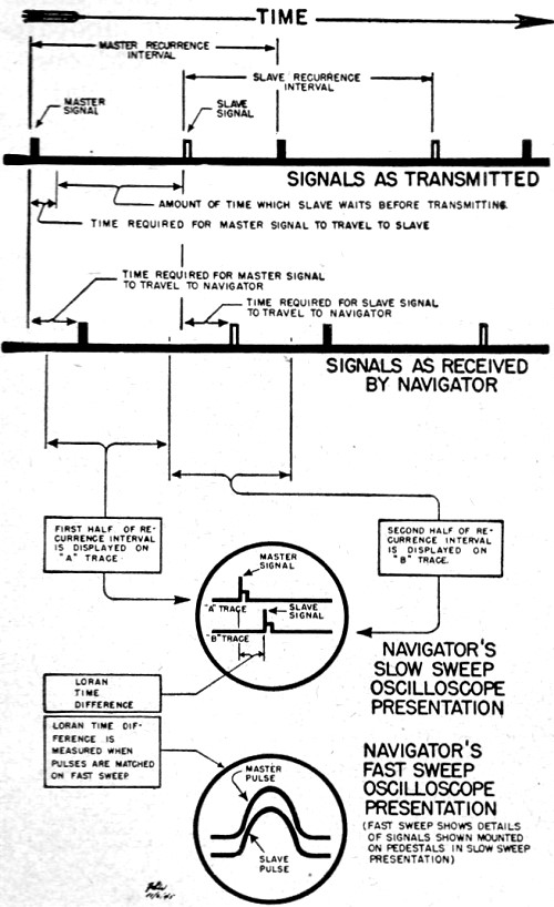
Fig. 5 - The Loran timing sequences. With this arrangement, the location of a ship can be pinpointed to within a quarter of a mile. The use of low frequencies and high intermittent pulsed power makes reception of the loran signals possible for hundreds of miles. By picking up another pair of stations (the slave station for one pair can also serve as the master station with respect to a station beyond it) another loran line of position can be provided so as to give another positional reference line. This second line can then intersect with the one plotted for the first pair of stations. If a third pair of stations can be received, the location of the ship can be determined beyond doubt. Many pairs of loran stations can utilize the same frequency channel by using different pulse repetition rates. In this way only one pair of pulses will show up as stationary ones for a particular group selection when viewed on the cathode-ray tube indicator. Fig. 5 shows how this information looks on the cathode-ray tube indicator. By selecting increasingly faster sweep rates for the CR tube of the receiver-indicator, the two pulses (master and slave) are measured first coarsely and then minutely down to the last microsecond difference of the time of arrival. The received pulses are first lined up on their respective pedestals. The master pulse is made to stop on the stationary pedestal either at the left end or the beginning. The slave pulse is then similarly lined up on the adjustable pedestal by means of an electronic knob control. The unit is then switched to a faster sweep of the tube to magnify the two pulses in question. The amplitude of one is increased or decreased as necessary so that one is fully superimposed on the other. When they merge to resemble a single pulse without overlap, the time difference is read directly in microseconds on a veeder counter. By knowing which pair of stations was used (shown on the station selector switch), for example, Pair 2, and the time difference (as shown on the Veeder counter), for example, 1220 microseconds, the ship's line of position may be established by referring to loran line of position 2-1220 on the map. Experienced personnel can take such a reading in a matter of seconds. They can also perform this operation continuously or as often as required.
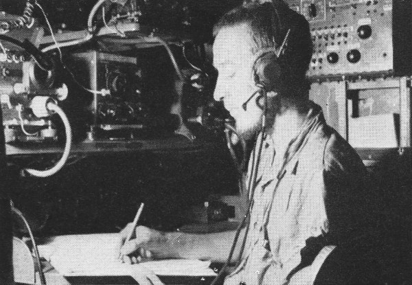
Fig. 6 - The Loran line of position.
Fig. 7 - The atomic shock wave. A few seconds after the "Able Day" bomb exploded at Bikini, a camera in the tower on the atoll recorded the atomic pressure wave thusly.
Fig. 8 - A v.h.f. direction finder on an aircraft carrier deck.
Fig. 9 - Typical radio compartment in a Navy PBY patrol bomber.
Fig. 10 - A simple type viewer used by signalmen to read messages sent with the otherwise invisible infrared light.
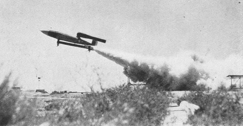
Fig. 11 - A guided missile is launched at the pilotless aircraft base of Naval Air Missile Test Center, Point Muqu, California. Guided missiles are high on the research priority list. Fig. 7 portrays one of the greatest and most important applications of electronics in warfare - the atomic bomb. This weapon represents new frontiers in electronics since every step of the bomb's development as well as its control involves the use of electronic apparatus and techniques. One heavy utilization of electronics is peculiar to the Navy. That is in the field of underwater sound detection, known as sonar. Sonar utilizes both audible (sonics) and inaudible sound (supersonics), chiefly the latter. This sonar equipment is used to detect submarines and surface vessels by means of the sound waves they set up in the water. It is the submarine's most useful electronic device when it is submerged. A fathometer is also considered a sonar device but this equipment operates only in a vertical plane. Sonar is comparable to radar inasmuch as it sends out a pulse and waits for the pulse to return before sending out further pulses. The time taken for the pulse to travel to its target and return is calculated and calibrated on an indicating dial in terms of distance. This is approximately 5000 feet-per-second with corrections for sea water density, salinity, and temperature. Sonar is also used in a modified form by aircraft in detecting submarines. One example of this is the sonobuoy. An airplane drops a sonobuoy into the water where it floats on the surface and releases a water-protected cable terminating in a hydrophone (equivalent of a waterproof microphone) into the water for a depth of several feet. The sounds picked up by the hydrophone modulate a radio transmitter in the, sonobuoy which, in turn, radiates the information from the sonobuoy antenna. This signal is picked up like radiotelephone signals by aircraft within ' horizon of range. The basic components of a shipboard sonar system include a driver unit to produce the sound signal to be transmitted, a projector to transmit the signal to the water and pick up the sound signals from the sea, a receiver-amplifier which amplifies these signals, and indicating equipment which gives the range of the target which reflected the outgoing signals. The bearing of such signals is determined by rotating the projector back and forth for maximum indication. A dome protects the projector and prevents water noise. Retracting gear hoists and lowers the projector as well as trains or rotates it in order to determine the direction of the sound. The receiver-amplifier, the indicating equipment, and controls are grouped together in an. assembly called the "stack" which is located near the maneuvering controls of the vessel. Auxiliary equipment such as the BDI (bearing deviation indicator and the attack plotter facilitate the use of sonar information in tactical applications. The driver is located close to the projector and retracting gear in order to keep the leads to the projector short. It is remotely controlled from the "stack." The projector is, of course, under water. When the projector is in operating position it extends beneath the keel of the vessel so that the sound beams may be directed in any horizontal direction without obstruction by the ship itself. Placing the projector a substantial distance below the keel helps to avoid interference produced by the noises of the ship itself. The retracting gear, mounted on a sea chest, is built into the hull of the ship. It raises the dome into the sea chest for protection when there is danger of damage by underwater obstructions or heavy seas. The motors for operating the retracting gear can be controlled from either the stack location or from the lower sound room. Extraordinary problems may arise from the fact that the projector dome protrudes below the vessel. Often submerged objects or even large fish collide with the dome, damaging it or putting it entirely out of commission. Fig. 8 is a high frequency direction finder on an aircraft carrier. This unit is used for locating the source of high frequency radio transmissions. It proved particularly useful in pinpointing the exact location of any submarine using high frequencies to transmit to other such craft. The information picked up by this equipment is then used to dispatch ships and aircraft to the scene for appropriate action. Other applications of' electronic equipment as used by the Navy include the radio gear carried by a Navy PBY patrol bomber of the Catalina type. See Fig. 9. Such craft did effective work in rescuing pilots and crews of other planes shot down or forced into the sea by engine trouble. They were also used to good advantage in patrolling missions and in flashing radio intelligence to other naval units. Fig. 10 shows a simple infrared unit used for communication by means of invisible light. Its ability to function with light waves that are invisible to the naked eye (electromagnetic frequencies lower than 375,000,000 megacycles) permits secret communication, particularly at night. This technique was used on most of the major fleet units at the time of the Mariannas campaign in World War II. Subsequently these units have been installed on all surface ships of the active fleet. Special filters and hoods have been developed to convert the standard Navy blinker light into an invisible light. These filters screen out all but the infrared component, thus the transmission is invisible to any observers except those equipped with specially-designed infrared receivers. Fig. 11 is a photograph of the "Loon," one of the many guided missile whose operation is dependent on electronics. The word "guided missile" is replacing the term "pilotless aircraft." It is an aircraft without a human pilot whose function have been replaced by electronics. In addition to not jeopardizing a human life, the guided missile is faster in response than human endurance and reaction time would otherwise permit. Technical officers and enlisted technicians in our modern Navy are receiving training and experience with all of these diversified types of electronic equipment. The training they are getting would be virtually impossible to duplicate elsewhere since the equipment on which they work is out of the range of most educational budgets. Electronic technicians now receive training comparable to that given pilots when the elaborateness of facilities and cost of the courses are taken into consideration. This same thing applies to similar educational facilities offered by the Army and Air Force and to some extent the Coast Guard and the Marine Corps. Very few of the men who received such training will dispute its value in civilian life. There are openings in the merchant marine, with civilian airlines, the CAA, and the various branches of the FCC as well as industry for men who fully understand the operation of such equipment. In time of peace or demobilization, radio or electronic technicians with military training enjoy excellent civilian employment opportunities. In time of national emergency they insure national security. And when war comes, they enable our country to substitute technology for human lives to win the only battle that really counts - the "last one."
Posted July 14, 2022 |
||