Radar on the Great Lakes |
|
An article title with both "radar" and "Great Lakes" (I lived a mile from Lake Erie) in the title is sure to catch my attention, as did this. Author Norman Schorr reports on the state of the art of radar equipment and usage for the purpose of maritime navigation. Research and development, along with an ample surplus of components left over from World War II facilitated a rapid adaptation of radar to many venues. Included among its applications were airway and waterway navigation, rocket trajectory tracking, security systems, speed measurement, weather observation, and aerial mapping. It is easy to take for granted the capabilities of radar today with having the accumulated knowledge of more than half a century on our side, but pioneers in the field had to think everything up anew. I have to admit to being familiar with what a "Pliotron" was prior to reading this article (it is Irving Langmuir's high frequency version of the Audion vacuum tube). Radar on the Great Lakes
Characteristics of six different types of radar installations now operating as test units aboard lake carriers.
The ship "George F. Rand" was assigned to Raytheon for their radar installation. The wave guide run from the antenna to transmitter is 70 feet. The indicator, housing a 7" PPI, can be tilted 45 degrees vertically and rotated through 45 degrees horizontally.
Table I - Characteristics of radar sets installed in Lake Carriers Association's Radar Operational Research Project. A dense fog suddenly descended on Lake Erie the morning of April 27, 1944. War shipping was at its height on this narrowest and most heavily-trafficked of the five Great Lakes. Within a few hours, two collisions occurred that cost the lives of 12 crew members and the loss of two cargo-laden ships. Without warning, the ore-carrier James H. Reed, collided head-on with the steamer Ashcroft, and sank quickly off Conneaut, O. Seventy-five miles west, the 4000-ton Frank E. Vigor, carrying a load of sulphur from Chicago to Buffalo, foundered and sank after colliding with the Philip Minch. Accidents like these are rare in Great Lakes shipping history. In fact, they have occurred on Lake Erie an average of once in 20 years since the advent of steel vessels in 1886. Stringent traffic rules, a special system of whistle signals, carefully routed up and down courses, and more recently radio telephone, radio beams and direction finders have combined to hold down the number of accidents. But still they have occurred - and when they do, the need for all-weather navigation instruments is emphasized. Though collisions caused by fogs have been infrequent, it is not unusual for skippers to be forced to drop the hook and wait until adverse weather conditions lift. Fog is encountered frequently in the spring and fall, and occasionally at other times. In the late fall, storms of sleet and snow can be expected. In a recent year more than 4,000,000 gross tons of cargo space were lost as a result of delays, collisions and groundings due to fog. Bad weather has held up ships for as long as 30 hours. As many as 100 boats have been fog-bound at the locks of the Sault Sainte Marie canal at one time. Great Lakes shippers took an immediate interest in radar as soon as the first successful marine application became known. Experience of the Coast Guard with radar during the war was watched as closely as security regulations permitted. A few sets were installed for brief trial runs, but extensive equipment for thorough experimentation was not available. It was not until after V-J Day that the shippers through their Lake Carriers Association initiated an active program, called the Radar Operational Research Project, to develop radar equipment best suited for Lake operations. They needed a navigation aid that would make possible close-range sailing in thick weather. Such a radar design would of necessity have high accuracy and definition at close quarters and would be capable of clearly showing shore lines, other ships, and the comparatively small buoys and channel markers. It was decided that the radar research men and engineers should be brought in direct contact with Great Lakes navigation personnel, so that each group might become familiar with the problems of the other. To this end, radar manufacturers were invited to install sets aboard a Lake cargo vessel during the 1946 season. Six manufacturers accepted the invitation and each was assigned a different ship on which to make an experimental installation that would operate on the Lakes. Upon conclusion of test runs and evaluation of results, minimum operating specifications will be set forth.
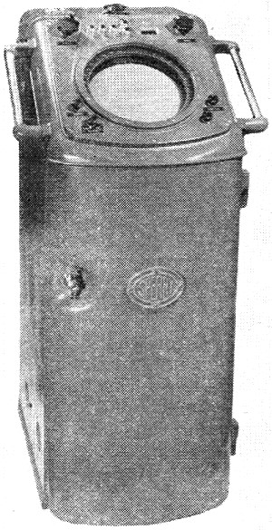
Indicator binnacle of the Sperry Gyroscope set houses 12" PPI and associated controls. Visible are range selector switch, variable range marker, bearing cursor, anti-clutter selector switch, and azimuth scale illumination control. Since the Lake Carriers Association represents 90 per-cent of the bulk cargo carried on the Lakes, this project is being followed with great interest in marine shipping circles, particularly with regard to inland waterway navigation. The busy Great Lakes are connected chiefly by rivers and dredged channels, some of which are no more than 600 or 700 feet in width. On an average trip a freighter will spend 25 to 30 per-cent of the time traveling in these confined waters. Among the most tortuous of these are in the entrance to the locks of the Sault Sainte Marie Canal between Lakes Superior and Huron; the Strait of Mackinac between Huron and Michigan; the St. Clair flats and Detroit River between Huron and Erie and the Welland Canal between Erie and Ontario. One of the narrowest and most inadequate of the dredged channels is the 700-foot wide Southeast Bend around Harsens Island, in the delta of the St. Clair River. It is in an area subject to sudden fog. Up and down traffic must squeeze through a 2-1/2 mile stretch of reverse bends that afford slight clearance. Each section the Bend sees about 20,000 vessel passages, carrying 90 to 100 million tons of ore, coal, grain and stone. Another tight spot is the 4-1/2 mile long West Neebish Channel, down bound from the Sault Canal. There, shores are as low or lower than a vessel's deck. Three miles of the channel are only 600 feet wide. Then it narrows for 5000 feet to a width of only 300 feet, and a depth of 24 feet, 8 inches - blasted through rock. Typical ones of the larger bulk cargo vessels are 600 feet or more long, 60 feet wide and travel at a speed of 11 to 13 land miles per hour. All in all there are about 800 commercial vessels of both American and Canadian registry plying the Lakes, almost half of them major type vessels. During busy times there is a two-way procession of ships going through the man-made locks and channels sometimes only 15 minutes apart. It is not difficult to visualize how impairment of visibility as a result of fog, sleet or other thick weather can seriously hamper traffic and even paralyze all navigation. During fogs, a phenomenon known as "aberration of sound" often occurs and contributes to make navigation more hazardous. On such occasions, "dead spots" appear on the Lakes. In these areas whistle signals from approaching vessels either cannot be heard or are distorted so that they seem to come from a source other than their true one.
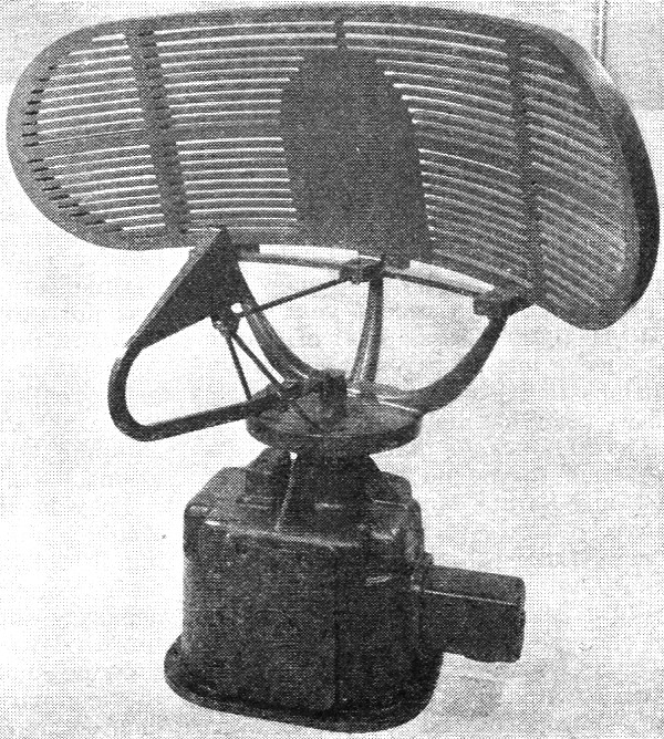
The parabolic reflector in the scanner component of the Sperry Gyroscope marine radar is 48 inches by 18 inches and rotates 360 degrees in azimuth at about 15 revolutions per minute. Contained in the splash-proof box are a driving motor (split-phase 1/8 horsepower squirrel cage induction motor) and a type SG synchro generator.
Modulator section of the Westinghouse set is located in the weatherproof base of the antenna pedestal. Action of the sine-wave oscillator, blocking oscillator, and thyratron tube, all shown in the picture. triggers the magnetron 2000 times per sec.
Radio frequency head of the Westinghouse set is also installed in the lower section of the antenna pedestal. It contains the magnetron oscillator, the crystal detector, local oscillator, and the high-frequency circuits associated with them. Other aspects of Great Lakes shipping that affect the job that radar is being called on to perform: Extreme length of travel in the Lakes from Duluth to Montreal is more than 1300 miles, but the main movement of ships is over the 1000-mile run between the upper Lakes and Lake Erie. Sailing season averages eight months, from about April to December, when the Lakes are free of ice. During this period a bulk cargo vessel may travel a distance equal to 2 1/2 times the earth's circumference at the equator, making port at least twice a week, for about 4 to 5 hours at a time. Compared to similar salt water vessels, these Lake carriers are somewhat larger and travel a few miles faster. During the war they delivered 4 1/2 times the total tonnage carried by all of America's merchant marine fleet on salt water. The master of one of these vessels cannot sail down the winding course of a river or channel by setting a compass course as is done in ocean sailing. He must follow a course marked by buoys of various sorts. At night his course is indicated by red and green lights on top of these markers, in addition to a heading taken on the range lights. When the skipper reaches an open lake area the widely separated up and down courses are followed by compass bearings in reference to special shore lights. Unlike the salt water master he cannot call on a harbor pilot, and a tug or two, to guide him into each of the 80-odd major ports on the United States and Canadian shores. He himself controls all the ship's movements from the time she raises anchor in the spring until she is laid up at the end of the season. An additional navigation problem is presented by the fact that many of the Lakes harbors are located at mouths of rivers. This was the picture when the radar manufacturers entered the program last year. The surface search sets they installed are principally simplified versions of the military and naval designs in widespread use during the war. They are designed for reliable operation without the attention of technical personnel. A navigator can operate a radar set after an hour of practice. Installed to give a maximum over-all view of the horizon, they furnish a continuous radar picture of the waters surrounding a ship, detecting the presence and location of shorelines, buoys, lighthouses and other vessels, with respect to the radar-equipped ship. Unlike military radar sets which included the so-called A-type indicator, the simplified marine radar sets depend solely on the PPI (Plan Position Indicator) to give the ship's navigator range and bearing information. This is accomplished by transmitting short pulses of ultra-high frequency radio energy at a rapid rate. These powerful radio waves are concentrated in a beam that is narrow in the horizontal plane and comparatively wide in the vertical plane. They strike objects in their path and are scattered. A small fraction of the original waves is reflected back to the rotating antenna, which in the interval between pulses serves as the receiving antenna. The reflected waves are amplified and fed to the fluorescent screen of a cathode ray tube where they are translated into spots of light. Factors governing the determination of a range reading include an object's size, shape, reflectivity, height, radar sensitivity and the wavelength of the radar set. But in general, radar horizon is the basic limiting factor for maximum range readings. In other words, a large object will loom higher on the horizon and will offer a larger reflecting surface; hence it will be able to be detected at greater distances. Since radio waves travel at a constant speed of 186,000 miles per second - like light - measurement of the time it takes for a signal to travel out and bounce back gives a reliable reading of range, or the distance between the ship and the object. On the sets in this project, readings are accurate to within approximately one or two per-cent. The face of the scope is calibrated in miles. Maximum range can be varied, in steps, depending on how large an area the operator wishes to scan. Concentric marker rings, equally spaced, can be superimposed on the screen of the cathode ray tube to aid in estimating range. The minimum range at which an object can be detected is 100 yards and the maximum with any of the sets is 50 miles. Transmitting a pulsed high-frequency signal is accomplished in this way: A high voltage pulse of microsecond duration causes a magnetron to oscillate. The resultant signal is sent to the antenna through a wave guide or coaxial system and directed into space by a reflector. Reflected energy is returned to the transmitter and detected in an r.f. section, where an i.f. signal is produced according to the superheterodyne principle. The i.f. signal is then amplified and detected. This time a video signal is the result and it is sent to the PPI indicator circuits, modulating a narrow electron beam. This beam shows up as a line of light on the scope face, and as it rotates, leaves a trail of objects visible to the observer as bright spots. In order that range information be accurate, indicator circuits are timed to start the electron beam's radial sweep each time the magnetron emits a pulse. As a burst of energy leaves the antenna the beam in the tube starts its movement toward the rim, and completes its journey in the interval between pulses. It is in this interval that the reflected signal is picked up by the antenna and fed to the PPI.
Indicator console in the Westinghouse installation. Below the seven-inch PPI and its controls and circuits are the low voltage power supply and the intermediate and video frequency amplifiers. Rotation of the antenna is linked to the magnetic deflection coils around the CRT, thus synchronizing the rotation of the electron beam. Since the high frequency energy travels in straight lines and at such great speeds, the reflections show up in proper bearing. As the antenna's beam sweeps across the bow of a ship, a radio line called a "heading flasher" is intensified on the PPI. When the picture is stabilized with North at the top of the scope, this flasher indicates ship's direction or heading. Equipment for azimuth stabilization is provided with some sets to furnish a bearing with respect to true North. This is possible when a ship is equipped with a gyro-compass. The radar picture is a continually changing one, and therefore the direction of any moving object may be noted. The path of another ship can be "observed" through a fog; and together with the use of navigational charts and standard techniques of seamanship, safe travel is made possible under adverse conditions. In addition, an indication of an object's physical composition also be learned from the blobs of light on the scope face. Shore lines are clearly outlined; rain appears as feathery masses. Buoys show up as small, but distinct dots. Ships may be accurately outlined, but more frequently resemble oval-shaped objects. A towing a barge often can be distinguished from two separate ships. To help the receiver provide an accurate scope picture under varying conditions, it is equipped with STC (sensitivity time control), FTC (fast time constant) and AFC (automatic frequency control circuits). STC suppresses "sea return," which is the reflection of signals from waves or particles of water. These signals impair observation of close target objects in rough weather. The STC circuit increases the receiver gain automatically with range, and is usually available to the operator in steps. FTC breaks up large signals caused by interference or by closely-grouped targets. It is particularly useful in detecting objects like channel buoy in heavy "sea return" or heavy rain. Automatic frequency control stabilizes receiver tuning with respect to the magnetron frequency. Since one antenna is used for transmission and reception, the sensitive receiver must be protected during transmission periods. This is accomplished by a transmit-receive tube which fires and effectively short-circuits the receiver every time an outgoing pulse travels toward the antenna. To prevent any reflected power from being wasted by going to the quiescent magnetron between pulses, an anti-transmit-receive tube that presents a large impedance to the signal is employed.
A GE parabolic reflector installed atop the pilot house of the "Ernest T. Weir." First Mate Gallaqher and Captain Hartman are inspecting the installation. The sets are designed to operate an alternating current power supply of 115 volts and 60 cycles, principally. For vessels where primary power is d.c., a suitable motor-generator set is used. A detachable viewing hood is provided to aid in observing the scope under unfavorable light conditions. One fundamental difference among the various sets is found in the operating frequencies. Four (Radiomarine, Sperry), Westinghouse, and Western Electric) are built to operate on the "X" band or three cm. wavelength. The Raytheon and GE models operate on the "S" band, with a 10 cm. wavelength. Supporters of the "X" band contend it provides better definition, better azimuth discrimination and hence is better for piloting a ship in close quarters. They also claim it furnishes greater range for a given radar sensitivity. "S" band advocates claim more reliability in bad, rainy weather, and less interference from "sea return." Determination of which band is superior for operation on the Great Lakes, is one of the hoped-for results of the project, although at the time of this writing it has not been decided whether all regularly-installed radar sets on Great Lakes ships will be limited to one band or the other. Other differences and similarities can be discovered in an examination of some of the different sets (see Table 1). One of the 10 cm. sets, Raytheon's "Mariners Pathfinder," was installed on the self-unloader bulk freighter George F. Rand in August. Operating frequency is 3070 megacycles ± 50 mc. Range scales are 1.5, 5, 15, and 50 miles. All exposed parts of the set are designed to withstand temperature from ,-40°C to ,60°C. The indicator, housing a seven-inch CRT and mounted on a pedestal, is movable. It can be tilted 45 degrees in a vertical plane and rotated 45 degrees in a horizontal plane. The transmitter, receiver, modulator and associated components are built in one unit. In the transmitter, pulse rate is 1000 cycles and pulse length is 0.4 microseconds. Peak power output is more than 15 kw. Source of radio frequency, of course, is the magnetron. In the receiver, a 30 megacycle i.f. is used; the r.f. band pass is 3 mc. The truncated parabolic antenna, 7 feet wide and 18 inches high, is installed on top of the ship's "A" frame, necessitating a waveguide run of approximately 70 feet. Antenna rotation is 7 r.p.m., both clockwise and counter-clockwise. It gives a beam approximately 3.5 degrees at half power points in horizontal plane. In the vertical plane the beam width is about 15 degrees. While proceeding on Lake Erie, gas buoys were observed at ranges of four to five miles. Ships were observed from 20 to 25 miles. A rainstorm, about 10 by 30 miles in area, was picked up and plotted. When the Rand entered the storm area, vessels and other targets were accurately observed. In the Detroit River channel, buoys, piers, and even rowboats were detected at limited ranges. The other 10 cm. set is the General Electric "Electronic Navigator" installed on the 8000 ton steamer E. T. Weir. It uses a 7-inch PPI, with fixed range scales of 2, 6 and 30 miles. A true or relative bearing can be obtained by direct reading from a movable bearing cursor with respect to a movable Azimuth scale. The 4 1/2 foot high viewing console contains all the radio equipment. Peak power output is the 7 kw, minimum output from the magnetron. Pulse length is 0.5 microseconds maximum, and pulse repetition rate is 1500 cycles per second. This frequency is determined by a blocking oscillator which simultaneously keys the modulator (pliotron tube) and the gate for the sweep generator.
Captain Hartman, a veteran of more than 40 years' service on the Great Lakes studies the PPI of the General Electric "electronic: navigator" aboard ship.
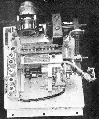
Modulator and r.f. head of Westinghouse radar set, including microwave section, a.f.c. control, and preamplifier. The reflector, a cast aluminum truncated parabola, makes about 11 r.p.m. and gives a beam width of five degrees to the half power points in the horizontal and 17 degrees to the half power points in the vertical. Cathode-ray tube deflection system of Radiomarine's radar set. The Radiomarine 3 cm. installation made in September on the A. H. Ferbert, operates on a frequency of 9320-9430 megacycles. It consists of three major units: oscilloscope indicator, antenna assembly and transmitter-receiver. A four-foot high indicator cabinet houses a 12-inch cathode ray tube, associated circuits and power supply. Rotating the CRT's electron beam in synchronism with the rotation of the antenna, for accurate bearing data, is achieved electronically without use of a moving coil. Single phase saw-tooth energy from synchronizer circuits is fed through coaxial cable to a size 5 G Synchro generator located in the antenna assembly, and three-phase modulated saw-tooth waves are produced. This energy then is sent through a 5 DG (differential generator) to a stationary deflection coil around the neck of the CRT, and this coil controls beam rotation. A 5 DG is not required on a ship without gyro compass. Since the differential generator is driven from the gyro compass, a stabilized picture always is obtained, so that "UP" position on the scope always points to North. A true or relative bearing can be obtained by merely flipping a switch, without recalibration. A gyro repeater scale is mounted at the head of the PPI, to indicate ship's course at all times, whether radar is on or off. Range can be varied from 1 1/2, to 5, 15 and 50 miles. The transmitter and receiver are built into a rectangular cabinet about five feet high, installed in the wheelhouse. Capable of delivering a peak power output of approximately 30 kw., the transmitter has two sets of pulse rates. For short distance operation, the pulse length is 0.25 microseconds and pulse rate is 3000 cycles. For longer ranges, the pulse length becomes 1 microsecond and the pulse rate 750 cycles. An 18-inch high parabolic cylinder antenna is constructed of curved, spaced stainless steel rods and rotates at 10 r.p.m. It uses a horn-type feed. Mounted on a standard 16 1/2 inch Navy flange, the lower section of the antenna assembly includes a driving motor, synchro generator, gearing and the wave guide rotary joint. The Westinghouse "X" band set was installed in July aboard the William G. Mather while the ship was underway. It gives readings for areas with radii of 2, 8 and 32 miles. On the wheelhouse roof a cut paraboloidal antenna is mounted, in a round plastic dome on a 5 1/2 foot pedestal. This pedestal also houses the driving a.c. motor, related drive gears and a" so-called synchro-tie system to coordinate the circular movement of antenna with rotation of electron beam.
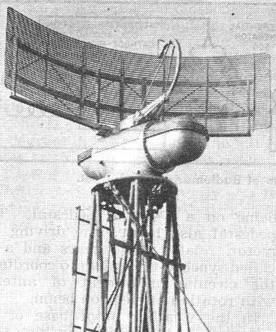
Antenna unit of the Radiomarine radar installed on top of the pilot house of the "A. H. Ferbert." The 18 inch high parabolic cylinder is constructed of spaced stainless steel rods and rotates at 10 r.p.m. Lower part of antenna assembly includes a driving motor, synchro generator, gearing and the wave guide rotary joint. In the weather proof base of the pedestal are the modulator, high voltage power supply, preamplifier and the r.f. head, which includes magnetron oscillator, the synthetic type crystal detector and local oscillator. The r.f. components are mounted in the antenna pedestal to cut possible power attenuation between transmitter and antenna, The 7-inch PPI scope is mounted on a four-foot high cabinet, on the ship's bridge, called the indicator console. Within this cabinet are the low voltage power supply, the i.f. and video amplifiers and related PPI circuits. The magnetron is triggered 2000 times a second by the action of a sine wave oscillator, blocking oscillator and thyratron tube, and emits a 0.4 microsecond pulse. Peak power out-put is more than 15 kw. Conducted by a horn-type wave guide to the radiator, the signal is sent out in a vertical fan pattern, two degrees wide horizontally and about 15° vertically. The radiator rotates at 12 r.p.m. In the receiver, a constant i.f. signal of 60 megacycles is provided by action of a klystron local oscillator. The Sperry 3 cm. set was installed on the Frank Armstrong in August, on a trip from Cleveland. It consists of an antenna assembly, viewing binnacle and transceiver unit which contains transmitter and receiver. Three internally-adjustable ranges can be set up on the 12-inch PPI; the first, from 100 yards to 2-5 miles, second, 500 yards to 6-12 miles, third, 1 mile to 20-40 miles. Fixed electronic range markers, appearing at regular intervals, are provided for each scale; in addition there is a variable marker. Range at this marker can be read to the nearest 100 yards directly from a counter. To permit clearer definition of close targets, the ship's own position indicator at the center of the scope can be expanded. This set can also be used in conjunction with the Coast Guard radar beacons, or racons, originally designed for aircraft navigation. By turning a control switch, the operator can bring in only signals from a beacon. These appear now as a series of short lines, coded to indicate the particular beacon. Provision is made so that the set will be able to operate with the new beacons designed for marine use. Pulse width is 0.25 microsecond and 1000 cycles a second for radar; 2 microseconds and 400 cycles per second for beacon operation. Peak power output is 35 kw. The parabolic cylinder reflector, four feet wide and 18 inches high emits a beam 2 degrees or less in the horizontal plane, and more than 15 degrees in the vertical plane. It rotates at 15 r.p.m. Last of the 3 cm. sets is the Western Electric radar which actually was the first of the six to be installed. Just before it went into operation aboard the John T. Hutchinson a "Miss Radar of the Great Lakes" christened the antenna with a bottle containing water from all of the Lakes. The installation consists of three basic units: the antenna on the pilot house, the indicator cabinet inside the pilot house, and the transmitter-receiver and synchronizer cabinets in the chart room. Pulse length of the transmitted signal is of 0.5 microsecond duration and a frequency of 1000 cycles per second. The truncated parabolic antenna, made of laminated aluminum, turns at 12 r.p.m. It emits a beam pattern 15 degrees in the vertical plane and two degrees in the horizontal. The range scale is variable and can be adjusted to cover an area with a radius from one to 40 miles. Because of delays in installation of some of the sets the operational phase of the research project will extend into the early part of the 1947 shipping season, according to C. M. Jansky, the electronics engineer who heads the project committee. For this reason recommended standards for future sets will not be issued until later this year. General reports have indicated that the sets have worked well. Ship personnel have caught on to radar quickly and are enthusiastic about its effectiveness. In one period when traffic approaching the St. Mary's River below the Sault locks was stalemated because of fog, two of the six radar-equipped ships were able to proceed straight to the locks and continue on their way. A performance like that is the best salesman radar can have. To simplify the task of observing the PPI picture in coincidence with navigation charts, two methods have been developed and are under consideration for future addition to the equipment. One will be to project a microfilm of a radar-piloting chart on the PPI screen; the other is to superimpose the scope picture directly on a navigation chart by means of a reflectoscope or similar device. In addition to its value for close range navigation, radar's ability to gather long-range information is expected to be helpful in expediting ship movements under the rapidly-changing weather conditions found on the Lakes. Ship operators predict a brilliant career for radar in one of its first and biggest peacetime assignments. In the words of Captain C. O. Rydholm, marine superintendent of the Cleveland-Cliffs Iron Company, which is a member of the Lake Carriers Association: "We believe radar will enable us to move cargoes with maximum speed, and, although our captains have set an enviable record of safe operations over the years, we believe radar will afford us an extra measure of safety for crews, cargo, and ships."
Posted February 2, 2023 |
|
")