Microwave Klystron Oscillators |
||
By now, engineers and scientists have managed to replace most vacuum tubes with solid state devices - at least for consumer products. The one place tubes remain are in microwave oven. Those klystron tubes operate in the 2.4 GHz band and typically output ranging from about 500 W to 2 kW. No doubt materials and methods have changed since the 1950s, but fundamentally klystrons of today are the same as klystrons then. Between this article and Part 1 that appeared in the April 1952 issue of Radio & Television News magazine, authors Joseph Racker and Lawrence Perenic provide a very nice introduction on the topic. According to the Wikipedia entry, the name "klystron" comes from the Greek verb κλύζω (klyzo) referring to the action of waves breaking against a shore, and the suffix -τρον ("tron") meaning the place where the action happens. The name "klystron" was suggested by Hermann Fränkel, a professor in the classics department at Stanford University when the klystron was under development. Microwave Klystron Oscillators By Joseph Racker* and Lawrence Perenic† Part 2. Concluding article of this series covering the use of reflex klystrons in modern circuitry.
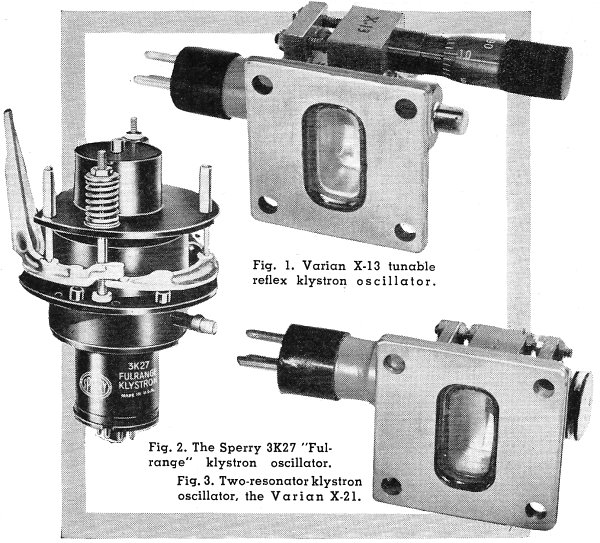
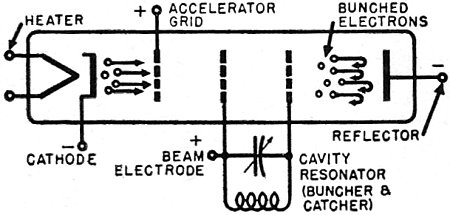
Fig. 1 - Varian X-13 tunable reflex klystron oscillator. Fig. 2 - The Sperry 3K27 "Full-range" klystron oscillator. Fig. 3 - Two-resonator klystron oscillator, the Varian X-21. While the two-resonator klystron, described last month, represents the simplest type for purposes of discussion and explanation, it is far from the simplest type to operate. For instance, it was seen in Part 1 how the alternating voltage across the catcher had to be timed to retard the bunches of electrons as they arrived. Since the rate at which these bunches arrived was governed by the frequency of the alternating voltage across the buncher, it was evident that both the buncher resonant circuit and the catcher resonant circuit have to be tuned to the same frequency for proper operation. Now, inasmuch as the resonant circuits associated with all klystrons are actually high-"Q" cavities, it becomes difficult to keep two or more such circuits in tune, thus tuning of a two-resonator klystron represents a serious problem. This problem of tuning is responsible, to a large extent, for the fact that of all forms of klystrons, by far the most common is the reflex klystron which utilizes only one resonant cavity. In the reflex klystron the same cavity is used for both bunching and catching. Instead of traveling only once through a straight drift-space, as in the two-resonator klystron, the beam is turned back on itself by a retarding field. This field is produced by a reflector plate which is maintained at a negative potential with, respect to the cathode, as shown in Fig. 4. The retarding field is strong enough not only to prevent the electrons from arriving at the reflector, but also to return them to the buncher. Upon examining Fig. 4 it can be seen that the method of producing velocity-modulation in a reflex klystron is basically the same as that used in a two-resonator klystron. An electron which passes the center of the buncher at the instant the alternating voltage across the grids is passing through zero has the same net voltage acting on it as it had when it passed through the accelerator grid. It, therefore, leaves the buncher with the same velocity it had when it entered. An electron which passes through the center of the buncher a little later, however, when the alternating voltage is increasing in the positive direction, has a higher net voltage acting on it. As a result, this electron leaves the buncher with a higher velocity than it had when it entered. It is seen, therefore, that in a manner similar to the one which took place in the two-resonator klystron, electrons passing through the buncher grids are either accelerated, decelerated, or remain unaffected by the buncher field, depending upon the phase and amplitude of the buncher voltage at the time they pass through. Reflector Bunching Action As was stated previously, the retarding field of the reflector is made sufficiently strong not only to prevent the electrons from arriving at the reflector, but also to return them to the buncher. In this way it becomes feasible to use only one pair of grids and one resonant cavity to act as both buncher and catcher. Since there is no longer a field-free drift space in which the velocity-modulated electrons can become bunched, "reflector-bunching" is the mechanism by which density-modulation is achieved in the reflex klystron, and the operation is as follows:
Fig. 4 - Schematic diagram of reflex klystron. Conditions for Oscillation In general, the condition for optimum operation of a reflex klystron is the same as for the two-resonator klystron, namely, the center of the bunches in the stream should pass through the catcher when the catcher field has its greatest retarding effect. Under this condition the greatest number of electrons lose the largest possible amount of power during the transit and the maximum power is extracted from the beam. In the case of the reflex klystron, which has no separate catcher, this means that the electron stream should be returned to the buncher when the buncher field has its maximum retarding effect. It can be shown that this condition is satisfied if the total drift time of an electron, i.e., the time it takes to travel from the buncher to the region of the reflector and return to the buncher, equals 1 3/4 cycles. That is, any change in the total reflector transit time from this value of 1 3/4 cycles results in a decrease in power delivered to the resonant circuit. If the total transit time is increased to 2 3/4 cycles, however, optimum conditions will exist once more because the phase of the catcher field will again be such as to retard the returning electrons. Similarly, for other values such as: (n + 3/4) cycles where n is a whole number such as 1, 2, 3, etc., oscillations may exist.
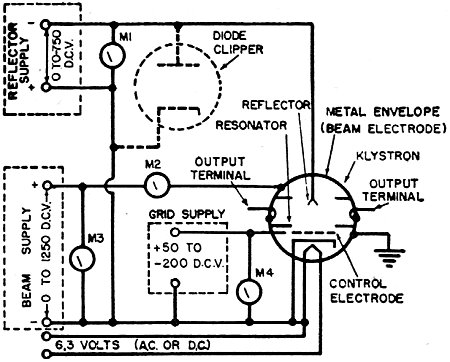
Fig. 5 - Correct power supply connections for a reflex klystron oscillator. This does not mean to imply that the reflex klystron will always oscillate if this transit time condition is met. If the d.c. beam current is too small, the power delivered by the bunched beam to the catcher may be less than the power dissipated in the buncher circuit. In this case there will be no oscillation, Therefore, a second condition is also necessary for oscillation to be maintained, namely, the d.c. beam current must exceed some minimum current, called the "starting current," which depends upon circuit and external load conditions. This starting current is inversely proportional to (n + 3/4), that is, it is greater for transit times of 13/4 cycles than it would be for, say, 3 3/4 cycles. If both the conditions just discussed, i.e., total transit time equal to (n + 3/4) cycles, and minimum starting current are satisfied, oscillations will always occur. Methods of Tuning In actual practice there are several ways in which the transit time of a reflex klystron may be adjusted to satisfy the first condition mentioned. Fig. 5 shows, schematically, how such a klystron might be connected to power supplies in a typical oscillator circuit. Four separate supplies are indicated; a heater supply, a grid-bias supply, a beam supply, and a reflector supply. Of these, the latter two can be adjusted (either singly, or in combination) to vary the transit time and thus provide optimum operation. Most frequently, however, a change in reflector voltage rather than a change in beam voltage is used to control the transit time because a change in beam voltage produces two effects that tend to compensate each other. Increasing the beam voltage results in a higher velocity for the electrons, which tends to increase the time it takes them to return to the catcher; while at the same time it produces a greater potential difference between the cavity and the reflector, which tends to return the electrons in a shorter time. Since a change in reflector voltage produces only the second of these effects, about one-third as much change is needed in the reflector voltage as in the beam voltage for equal results. In addition, the reflector is a high-impedance electrode which draws no current and, therefore, the controlling elements (usually potentiometers) need not be capable of handling any appreciable amounts of power.
Fig. 6 - Characteristics of reflex klystron. Since changing the transit time in a klystron is equivalent to varying the operating frequency, it is seen that by adjusting the reflector or the beam voltage of these tubes, the frequency may be changed. This behavior is known as "electronic tuning," and is utilized in practice to change the oscillating frequency by a comparatively small percentage. The main frequency controlling element in the reflex klystron is the resonant cavity which forms part of the buncher-catcher. By mechanically compressing the cavity, the volume of the cavity and the spacing of the grids connected to it are caused to change and, in this way, alter the oscillating frequency. This is called "mechanical tuning." In practice, both of the above methods are used, as follows: The mechanical tuning is adjusted so that the operating point falls in a region of operation where the frequency can be shifted a reasonable amount in either direction with electronic tuning without too much change in output power. The beam voltage and grid bias are adjusted to provide at least minimum starting current. Once the tube is oscillating, the reflector voltage is adjusted to optimize the transit time and thus provide maximum power output within a given "mode" of oscillation. Typical Behavior Curves Klystron oscillators, in general, are characterized by the existence of discrete "modes of oscillation." (The word mode is used here to denote certain limited regions of electrode voltage within which oscillation occurs. Within a given mode, the frequency of oscillation changes continuously from one end of the mode to the other as the electrode voltage is changed.) The following are typical curves which illustrate this behavior: Fig. 6 illustrates the so-called "reflector characteristics" of a reflex klystron, and shows both the variation of power output and the variation of frequency with reflector voltage. As can be seen from the lower curves, there are several discrete ranges of reflector voltage at which the tube will oscillate and supply power to the load. It is these ranges of operation which were previously defined as "modes." Inspection of the lower curves further reveals that the r.f. power outputs are not the same for all modes. In general, the maximum power output is greater at the higher reflector voltage modes. However, it is important to keep in mind that while the maximum power output obtainable may differ from one mode to the next, the frequency at the point of maximum output in each mode is exactly the same - being the resonant frequency of oscillation of the cavity.
Fig. 7 - (A) The difference-frequency type of a.f.c. system. (B) Block diagram of the absolute-frequency type of a.f.c. system. In addition to showing the power output vs reflector voltage characteristics just discussed, Fig. 6 also gives the frequency deviation vs reflector voltage characteristics of a typical reflex klystron. These curves are drawn in the upper portion of the graph and show the variation of output frequency with changes in the reflector voltage within any one mode. As was previously defined, this shifting of the operating frequency with reflector voltage is called "electronic tuning." The upper curves show that the range of tuning also varies with the mode, but in the opposite sense; in general, the range is smaller at the higher reflector voltage modes, making the operating frequency less susceptible to change for a given ripple in the reflector voltage supply. Since the modes with the highest output have the smallest electronic tuning range, a compromise must often be made between the value of reflector voltage which will yield the highest power output and a value of reflector voltage which will result in the greatest tuning range. Automatic Frequency Control There are times when a very high degree of frequency stability is required and then some form of a.f.c. is usually employed. Most a.f.c. systems operate to minimize the difference between the frequency of the klystron oscillator and some standard of reference. In most radar applications, the standard of reference is the transmitter frequency plus or minus the intermediate frequency. This type of a.f.c. system can be thought of as a difference-frequency system. Another type of a.f.c. system used for the beacon local oscillator of an airborne radar uses a precision resonant cavity as the standard of reference. This type of a.f.c. system can be thought of as an absolute-frequency system. An example of the difference-frequency type of system is shown in the block diagram of Fig. 7A. The mixer, Lt. stages, and detector are similar to those found in any radar receiver. During transmission a portion of the transmitted pulse leaks through the "transmit-receive" section and is fed to the mixer in the same manner as would be a received signal. The mixer, in turn, produces an i.f. output which is applied to the discriminator of the a.f.c. system. The discriminator is able to distinguish. between signals which are above the desired frequency and those which are below, and is able to produce an output voltage which is positive in one case and negative in the other. This d.c. voltage is amplified and added to the reflector voltage of the local-oscillator klystron in such a way as to maintain the output of the mixer at constant intermediate fre-quency. In the absolute-frequency type of system, a high-"Q" reference cavity is employed as the standard. A block diagram illustrating the basic circuit is shown in Fig. 7B. As can be seen from the diagram, a portion of the r.f. output from the klystron oscillator is fed to an r.f. discriminator which is capable of producing an output voltage in proportion to the difference between the oscillator frequency and the resonant frequency of the cavity. This correction voltage is amplified and added to the reflector voltage of the klystron in such a way as to make the oscillator frequency the same as that of the reference cavity. Details on Reflex Klystron
Fig. 8 - Typical cavity for 8·12 cm region.
Fig. 9. Simple wave guide-to-coax transition.
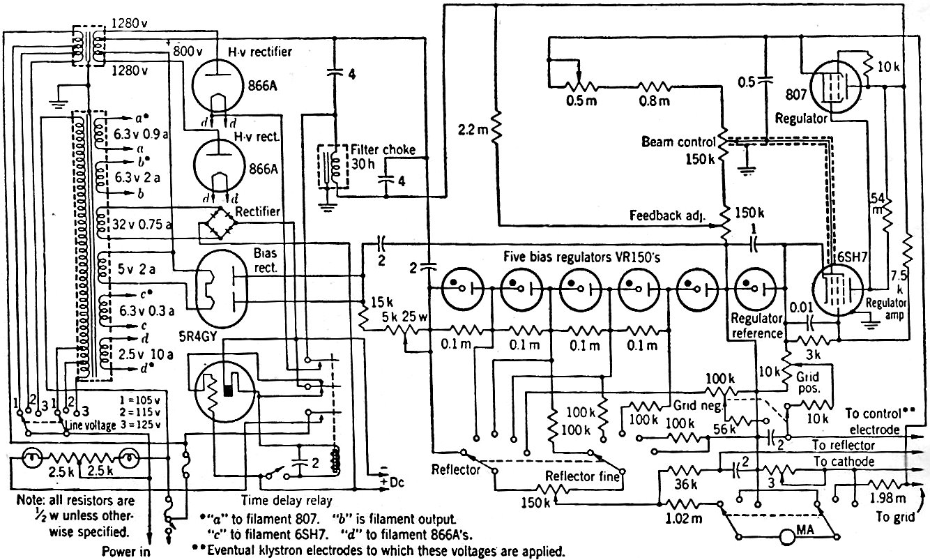
Fig. 10 - Schematic diagram of a satisfactory power supply for reflex klystrons.
Fig. 11 - A 2K39 reflex klystron mounted on wave guide with which it is used.
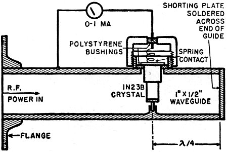
Fig. 12 - Simplified crystal detector circuit. Although all reflex klystrons behave electronically in a similar manner to that described in the foregoing paragraphs, in the past few years different mechanical design approaches have resulted in the development of several distinctive types of tubes. Since the most noticeable feature of a reflex klystron is its resonant cavity, a convenient grouping is according to the location of the cavity; that is, whether it is built into the tube (integral cavity), or external to it (external cavity). The 3K27 reflex klystron, for example, is an integral cavity type and is illustrated in Fig. 2. The octal tube base serves to connect the proper operating voltages to the heater, grid, and buncher. Part way up the tube, pointing to the right, is a short length of rigid coaxial line which forms the output lead. The microwave oscillations in the cavity are coupled out by means of an inductive pickup loop located inside the cavity and sent through this coaxial line to the output connector where it is available to do useful work. The cavity proper is the cylindrical portion of the tube which starts just below the coaxial output line and extends upward as far .as the helical springs. The mechanical tuning mechanism, not shown in the photograph, consists of helical springs, levers, tuning knob, screw, and a right-angle bracket. By rotating the tuning knob, the tuning screw moves either in or out of the bracket. This causes the levers to change position. Since the levers, in turn, are connected to the movable wall of the cavity, the cavity shape becomes distorted and the frequency is changed to suit the new cavity dimensions. The 3K27 reflex klystron, with a full-range tuner, is capable of covering the entire frequency range of 770 to 1150 megacycles by rotation of a single knob, and with an average power output of about 1 1/2 watts. A second type of reflex klystron, known as the 2K28, uses an external cavity. In this type of tube the resonant cavity does not lie completely within the tube, but is chiefly external to it. In addition, the tube is constructed mainly of glass and does not have any tuning mechanism built in. The tube base is located at the bottom and serves to connect the proper operating voltages to the tube, as before. The electron gun occupies the region just below a lower copper disc which protrudes through the glass. This copper disc and the one above it form only a part of the cavity. The remainder of the cavity, whatever type it may be, must make contact with these two projecting discs. A typical cavity for the 8 to 12 cm region is shown in Fig. 8. The 2K28 fits in the hole in the center of the cavity with its discs making contact with the cavity walls. Mechanical tuning is accomplished by turning the tuning knob, shown at the right-hand side of Fig. 8, which causes the sliding plunger (shown in the cutaway section) to move either toward or away from the klystron. This motion changes the volume of the cavity and thus the frequency of operation. The microwave oscillations are coupled out by means of an inductive pickup loop and fed through the short section of coaxial line shown on the left-hand side of the cavity. The 2K28 reflex klystron has a lead protruding through the top of the glass envelope which is used to connect the reflector voltage to the tube. Although the 2K28 was designed to operate in the 10 cm. range, oscillations have been obtained as low as 1000 mc. by using the proper external cavity. The average power output of this tube is about 70 mw. Having discussed the theoretical aspects of satisfactory klystron operation and briefly described the physical details of some external and integral-cavity types, this article concludes with some notes on the construction of an actual oscillator. Fig. 11 shows a 2K39 reflex klystron, an integral-cavity type, mounted (within a Plexiglas safety cover) directly on the wave guide with which it is to be used. The tube is supported by means of a metal bracket to a wave guide-to-coax transition. This transition, or adapter, consists of a section of wave guide 1" x 1/2" in cross-section, shorted at one end, and with a probe projecting into the guide as shown in Fig. 9. The upper end of the probe ends in what is known as an "SKL" fitting, * which mates with the "SKL" fitting on the output line of the klystron. Use of such a direct mechanical coupling between the klystron and wave guide eliminates the annoying tendency of the output power to vary - which occurs when non-rigid coaxial lines are used at these frequencies. Moreover, the power output obtainable from the oscillator is greater due to the decrease in length of the coupling line. To operate the oscillator shown, two additional items are required: the first is a power source capable of supplying the voltages previously discussed, the second is a blower of approximately 50 cfm (cubic feet-per-minute) capacity to cool the klystron at maximum ratings and to improve the frequency stability. Although several excellent supplies are available commercially, the experimenter who wishes to construct his own will have to exercise particular care with the reflector supply. The supply should be designed to have a low impedance to reverse current to prevent a transient condition or modulating voltage from driving the reflector positive - a condition which can seriously damage the tube. A satisfactory supply should not have more than a 50,000 ohm bleeder across its output. In addition, all three d.c. supplies should be characterized by very low ripple content. The reflector supply variation, in particular, must be held to better than a small fraction of one volt, while the beam supply need be only one-half as good (on a percentage basis). Fig. 10 gives the schematic of one of many supplies which has been found to give satisfactory performance. Note in particular that the reflector supply is exceptionally well regulated. This oscillator may be tuned to any frequency in the 7500 to 10,300 megacycle range with a power output of better than 300 mw. In the event a power bridge is not available, oscillation can be detected by means of a crystal rectifier and .c. milliammeter arrangement shown in Fig. 12. Adjusting the reflector voltage for a maximum indication on the 0-1 milliammeter is about the most feasible way of getting started. Further refinements will almost suggest themselves. * Sperry Gyroscope Co., Trademark * Pres., Joseph Racker Co. † Chief Electronic Engr., Bogart Manufacturing Corp.
Posted January 31, 2019 |
||