Microwave Klystron Oscillators |
||
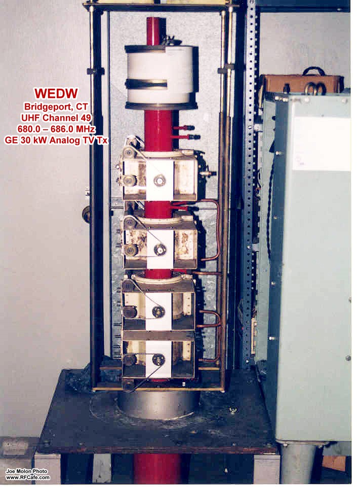
The microwave klystron was invented in 1937 by brothers Russell and Sigurd Varian. If you have been in the microwave design business for a couple decades, you undoubtedly recognize the company name of Varian Associates, especially if you worked in the aerospace or defense electronics business. There is a video on YouTube of a segment on Varian done sometime around 1990 by Walter Cronkite. There is also a historical piece on Varian Associates on the Communications & Power Industries website. This circa 1952 article covers the fundamentals of klystron operation and reports on the increasing use of klystrons in high frequency applications - including by amateur radio operators exploring the top end of the bands. Part 2 of this article appeared in the May 1952 issue of Radio & Television News magazine. RF Cafe visitor Joe Molon (KA1PPV) sent some photos of a klystron he worked with at television station WEDW in Bridgeport, Connecticut. See those pics and his note below. Microwave Klystron Oscillators
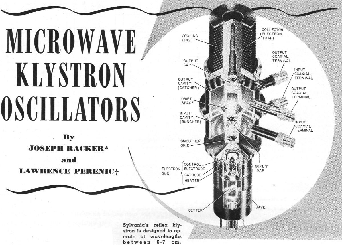
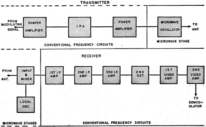
Part 1. Practical operating data on klystrons as used in present-day communications equipment. Microwave frequencies are being used to an ever-increasing degree in commercial television and communications links, amateur transmission, and a long list of governmental and industrial electronic devices such as radar, instrument landing, guided missiles, and air traffic control. Consequently, the field of microwave techniques offers an excellent opportunity to technicians and engineers, as well as providing interesting equipment for ham operation. Fig. 5 is a block diagram of a typical transmitter and receiver operating at microwave frequencies. As seen in this diagram, all stages except the microwave oscillator in the transmitter and input circuit and local oscillator in the receiver, operate at conventional frequencies. This illustrates a very important fact, namely, a thorough understanding of microwave oscillators and their associated circuits provides the reader with a very substantial basis for servicing and building many microwave systems. In other words, generally speaking, a microwave transmitter is no more than a conventional type transmitter which uses a microwave oscillator. A microwave receiver is a standard superheterodyne circuit using a microwave local oscillator and input circuit. There are a number of methods of generating energy at microwave frequencies including lighthouse oscillators, magnetrons, traveling wave tubes, and klystrons. The klystron oscillator, which is the subject matter of this article, is by far the most commonly used oscillator, particularly in commercial equipment. Sylvania's reflex klystron is designed to operate at wavelengths be tween 6-7 cm.
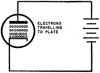
Fig. 1 - Electron flow in a diode tube.
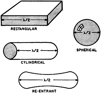
Fig. 2 - Several common types of cavities. For reasons that need not be discussed in this article, it is extremely difficult and inefficient to generate microwave energy using conventional techniques and tubes. Of the microwave oscillators listed, only the lighthouse tube uses standard oscillator circuits. This type of oscillator, however, has an upper frequency of about 4000 mc. All of the other oscillators, sometimes called transit time oscillators, employ new and different techniques of oscillation. Since entirely new techniques are involved, the authors have divided this article into two parts. The first part describes the basic theory of klystron operation so that a reader who has never had any previous microwave experience can understand how it works. The second part covers the practical aspects of the klystron oscillator, namely, its construction, characteristic curves, methods of tuning, modulation, and servicing. Needless to say, the reader cannot absorb the material presented in the second part unless he understands the theory outlined in the first part. Conservation of Energy Law A very familiar universal law - conservation of energy - which is rarely used in electronic theory becomes very important in klystron and other transit time oscillator operation. They are called transit time oscillators because the energy required to sustain oscillations is obtained from the electron stream while it is in transit between cathode, or electron gun, to plate, or collector. In order to understand how this energy is transferred, the conservation of energy law must be applied to the electron flow. Consider the flow of an electron that leaves the cathode of the diode, shown in Fig. 1, and travels toward the plate. When the plate is positive with respect to the cathode, the electron is accelerated toward the plate. Whenever any mass, including an electron, is accelerated it picks up energy. From the law of conservation of energy it is known that this energy must come from some other element in the system. Actually, in this case, the energy comes from the battery. This is most easily seen at the instant that the electron actually reaches the plate. At this time the electron would normally neutralize a positive charge and the plate potential would decrease. However, the battery has been expending energy and drawing an electron away from the plate, as the transit electron approaches it, so that when the electron actually reaches the plate there is no net change in charge and the plate potential remains constant. The most important fact, however, is that when an electron is accelerated, it gains energy, and this energy comes from some element in the system. Similarly, if the plate potential is negative, the electron is retarded, or slowed down, by the plate. When an electron is retarded, it is giving up energy. Thus when it approaches the plate it repels an electron on the plate toward the battery. This; in effect, means that energy is being returned to the battery. Now let us apply this law of conservation of energy to an electron flowing in an electric field such as can exist in the cavity described in a later paragraph. If the electron is accelerated by the field it is gaining energy which must come from the field and make it weaker. Hence an electron that is accelerated by the field causes the field strength to decrease. Conversely, an electron that is retarded by the field, loses energy to, and increases the field strength. In this article, the direction of the electric field will be depicted by an arrow and the magnitude of the field by length of arrow. An electron flowing in the direction of the field is accelerated by it (some texts use the reverse convention), while an electron flowing against the field is retarded by it. Flow in Cavity Resonator At microwave frequencies a special type of tuned circuit, known as a cavity resonator, or simply a cavity, is required. The cavity is a hollow metallic box which can be rectangular, cylindrical, spherical, or a number of other shapes. Several common types of cavities are shown in Fig. 2. The cavity is usually about one-half wavelength long (wavelength as measured in the cavity), although it can also be any multiple number of half wave-lengths long. In any tuned circuit, such as the conventional LC tank at conventional frequencies, there is a continuous exchange of energy from magnetic to electric field, and vice versa. For example, in the LC circuit the energy stored in the magnetic field around the coil is transferred into the electric field, building up in the condenser, as the current in the circuit declines. During the next half cycle, as the condenser discharges, the condenser electric field energy is transferred into the magnetic field which is being generated around the coil.
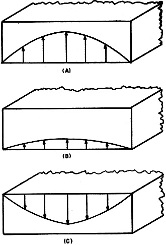
Fig. 3 - Electric fields in rectangular guide.
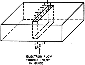
Fig. 4 - Electron stream flowing through the slot in a rectangular wave guide.
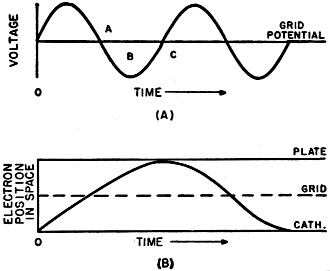
Fig. 5 - Block diagram of a conventional microwave transmitter and receiver. In a cavity this continuous exchange of energy takes place in the air within the cavity. In a one-half wavelength rectangular cavity, for example, the electric field exists sinusoidally along the length of the cavity as shown in Fig. 3. The field is always maximum at the center and reduces to zero at the ends. The magnetic field in the cavity also has a sinusoidal variation, being maximum at the ends and be-coming zero at the .center. In Fig. 3, three instantaneous values of the electric field distribution are shown. In Fig. 3A, the electric field is at its maximum intensity. In Fig. 3B, which occurs a short time later, the entire field is declining (and beginning to build up the magnetic field). In Fig. 3C, the field has undergone a half-cycle of opera-tion (since 3A) and is at its maximum negative value. Just as in any tank circuit, the intensity of the electric field during each successive cycle would decrease slightly, due to small energy loss - equivalent to resistive loss - unless some method of replenishing this energy is available. This can be done by use of an electron stream. Assume that, as shown in. Fig. 4, a small slot is inserted at the center of a rectangular cavity and an electron stream is directed through this slot. When the electric field of the cavity is so directed (positive half-cycle) that it accelerates the electrons, energy is transferred from the field to the electrons and the field intensity diminishes and oscillations are damped out. However, if the field is so directed (negative half-cycle) that it retards the electron flow, then energy is transferred from electrons to field, and oscillations are sustained. This is the basic principle of klystron operation. Velocity Modulation In the foregoing example, if the electron stream were passed through the cavity with uniform intensity, it would increase the field during one half-cycle and decrease it during the next half-cycle and there would be no net exchange of energy. However, if we could arrange the electron stream so that the density of electron flow during the field negative half-cycle is much greater than the density during the positive half-cycle, then there would be a net exchange of energy from electron stream to the field. The process by which the electron beam is "bunched" in this manner is known as bunching or "velocity modulation." The velocity modulation action is best understood by considering the operation of the simplest type of velocity modulation oscillator called the positive grid, Barkhausen-Kurz, or retarding field oscillator. In this type of oscillator, shown in Fig. 6, the grid is operated at a positive potential with respect to cathode and plate, and the plate is negative with respect to the cathode. The operation of this circuit will be considered first under d.c. conditions and then with an a.c. voltage applied to the grid. In addition, although the complete action involves many electrons, it will be simpler to first investigate the behavior of a single electron. Then, later; the reasoning thus obtained will be extended to entire groups of electrons. Consider the flow of an electron leaving the cathode of the tube shown in Fig. 6 with the tank circuit shorted out (no a.c. voltage on grid). As an electron leaves the cathode it is accelerated toward the grid by its high positive potential. By the time the electron reaches the grid its velocity is high and it may either hit the grid, delivering its energy in the form of heat, or - more likely - it will pass through the space between grid wires into the region between grid and plate. In the grid-plate region the electric field is in the opposite direction because the plate is negative with respect to the grid. This field tends to slow down the electron and for this reason the oscillator is sometimes called the "retarding field" oscillator. If the plate voltage is sufficiently negative, the electron will come to rest at some point in space between the grid and plate. The attraction of the grid then causes the electron to reverse direction and move back toward the grid. The electron then swings back and forth past the grid (path M, N, 0) until it eventually hits one of the grid wires. The phenomenon is very closely parallel to that of the oscillation of a damped pendulum (damped because electron loses some energy during each cycle). If no other elements were introduced in the circuit many individual electron oscillations would occur in the space between plate and cathode, causing equivalent energy oscillations in the grid circuit. The exact phase and amplitude of these oscillations between any two electrons would depend upon the time at which the electrons were emitted and the space charge at that time. It is obvious that under these conditions no useful oscillator energy can be supplied to the grid circuit, since the electron oscillations are random and cancel each other. Now assume that an a.c. voltage is superimposed upon the grid. (tank circuit no longer short circuited). The frequency of this signal is so high that by the time the electron travels from cathode to the grid, the voltage has changed one-half of a cycle, for example from maximum positive to maximum negative, or from zero to zero, and so on. This is shown in Fig. 8 where (A) plots the a.c. voltage and (B) the oscillatory (no energy loss) electron path. Let us define the velocity, vo, as the velocity of the electron at any point in the cathode-plate space with grid potential at the d.c. value shown in Fig. 6.
Fig. 6 - The electron motion in a positive-grid (Barkhausen-Kurz) type oscillator having constant electrode potentials.
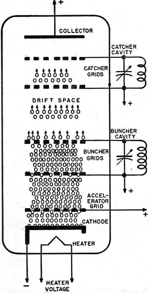
Fig. 7 - Basic representation of klystron.
Fig. 8 - Graph of (A) grid a.c. voltage and (B) electron position in space leaving cathode when the time base is equal to zero. Consider the relative velocities of the electrons leaving the cathode during grid a.c. potential of A, B, and C shown in Fig. 8A. An electron leaving during time A, travels at a velocity less than vo in the cathode-grid plane because during this time the grid is always at a negative a.c. potential. It loses more velocity between grid and plate since during this time the grid is positive. Thus, its over-all velocity is less than vo. An electron leaving the cathode with grid potential at B will travel at about vo, since during both its cathode-grid and grid-plate paths the grid is positive half the time and negative half the time. Finally, an electron emitted at time C will travel at a velocity greater than vo, since the grid is positive (a.c.) when it is in the grid-cathode plane and negative in the grid-plate plane. It is readily seen that the electrons emitted at time C tend to catch up with electrons emitted at time A so that electrons will tend to oscillate in bunches instead of completely at random. Now useful oscillatory energy can be supplied to the grid circuit. Klystron Operation Basically, the klystron, as shown in Fig. 7, consists of an electron gun, "buncher" and "catcher" grids, and a collector. The electron gun is similar to those found in cathode-ray tubes and functions to provide a steady stream of electrons. The buncher and catcher grids are part of the cavity resonators, slotted in the center using the same principles shown in Fig. 4. The electron stream is velocity modulated by the buncher grids and converted to microwave energy in the catcher grids. Electrons passing through the catcher grids are removed from the circuit by the collector. The entire assembly is enclosed in a vacuum tube. The electron gun directs a constant intensity stream of electrons through the buncher grids. The electric field, due to the cavity action between these grids, is varying sinusoidally. Accordingly, some electrons are accelerated, some maintain the same velocity, and others are retarded as they pass through these grids. The electrons emerge from the buncher having various velocities, but the electron stream still has an essentially uniform density. The electrons then flow through a field-free "drift space." It is assumed, for simplicity, that in this region there are no d.c. or r.f. fields, and that any space-charge effects are negligible. In this drift space, the electrons that were speeded up by the buncher begin to catch up with the slower moving electrons ahead of them. In a similar manner, the electrons which were slowed down by the buncher lag behind more and more until they are overtaken by electrons that left the buncher at a later time. This bunching process, similar to that occurring in the positive grid oscillator, eventually results in the breaking up" of the electron beam into groups, or bunches, of electrons. These bunches of electrons are separated by regions in which there are comparatively few electrons. The electrode arrangement thus far described is useless in the sense that no output signal has been obtained. In principle, an ordinary plate might be installed at the end of the drift space and be used to collect the signal from the electron beam. The voltage of the plate would rise and fall as if was struck by the bunches of electrons. Unfortunately this method of signal collection is not practical because the frequencies at which velocity modulated tubes operate are so high that stray capacity of the external load circuit would short circuit this energy. Therefore another cavity is used to absorb this energy. This cavity, known as the catcher, is placed at the point in the drift space where maximum bunching occurs. The field of this cavity is so phased that it always is negative with respect to the bunched electrons. Hence energy from the bunched electrons is transferred to the catcher cavity and oscillations are sustained. The field is positive across these catcher grids during the time that there is a region of relatively few electrons and, therefore, little loss of energy occurs during this part of the cycle. Proper. phasing between catcher and buncher grids is effected by feeding back some of the catcher cavity energy into the buncher cavity. The remainder of the oscillator energy is coupled through a coaxial cable to the desired load. After passing the catcher grids, the electrons are moving at a greatly reduced velocity and are finally removed from the tube by a positive collector plate. The collector plate potential must be positive enough to attract all the electrons, but not so positive that electrons will strike at a high velocity and cause secondary emission. It is obvious that any random electron flow detracts from the over-all efficiency and stability of the system. Hence, the importance of effective removal of electrons after they have passed catcher grid. In the second article on this subject, some of the practical aspects of klystron operation will be considered. (Concluded next month) * Radar Consultant. † Chief Electronic Engr., Bogart Manufacturing Corp. Varian Associates Story by Walter Cronkite January 8, 2016 Update: RF Cafe visitor Joe Molon (KA1PPV) sent the following after seeing this article (posted with permission).
WEDW CH 49 Transmitter Klystron
Posted July 19, 2022 |
||