Master Tube Tester |
||
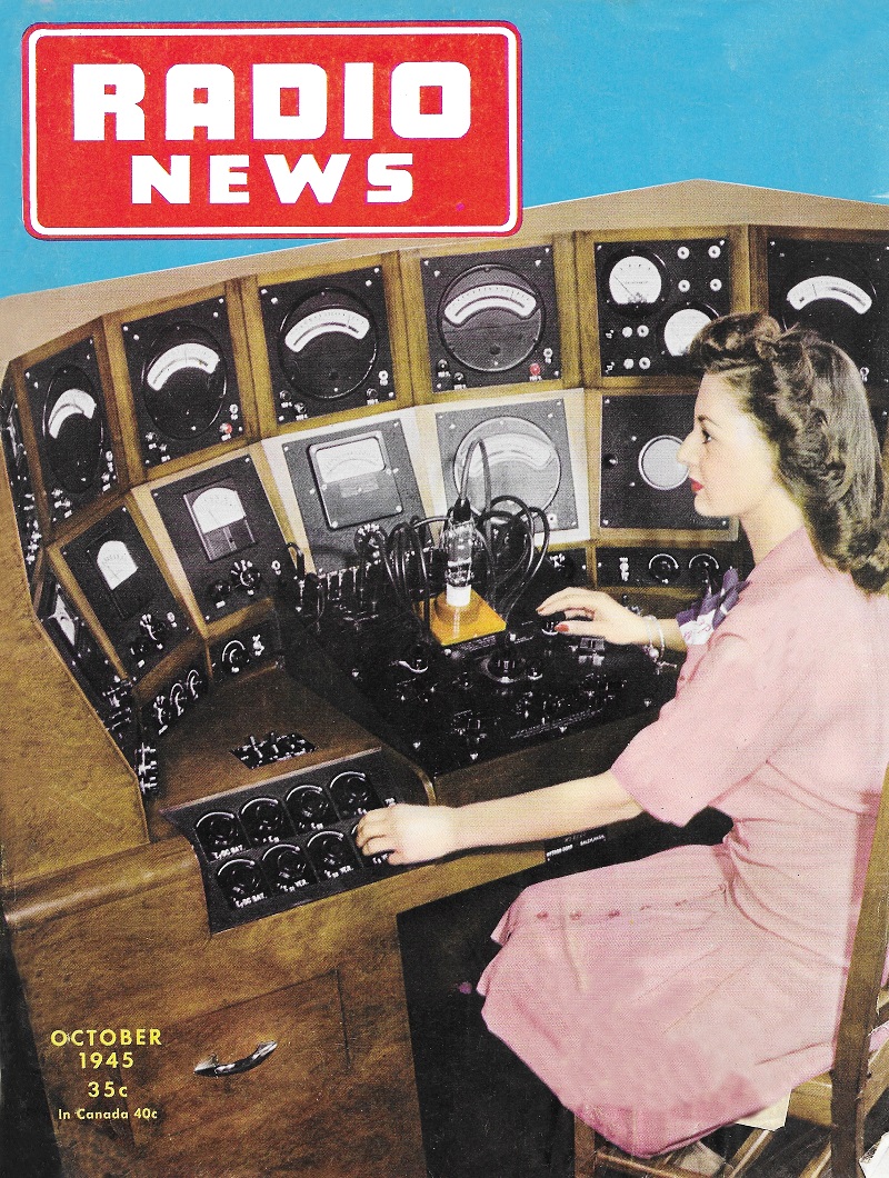
Master Tube Tester featured on the cover of the October 1945 issue of Radio News. Founded in 1921 in Salem, Massachusetts, Hytron Corporation started out making vacuum tubes, then after being bought by CBS (Columbia Broadcasting System, the TV broadcasting people) in 1951 they moved into the realm of semiconductor production. This story from a 1944 issue of Radio News magazine extolled the virtues of Hytron's Master Test Station for its ability to quickly and accurately measure a wide variety of tubes. Auto-ranging voltage regulators, parallax-free meters with auto-ranging scales, safety fusing, and easy servicing were among it notable features. To me, a parallax-free meter is one with a mirror behind the needle used to assure the operator is looking straight-on at the scale, but in this case it meant the array of meters was arranged in a semi-circle so that the operator was naturally looking perpendicular to the meter faces from a fixed vantage point. The level of automation no doubt reduced measurement errors and allowed a less skilled operator at the test station. Here is an interesting reproduction of a pamphlet published by CBS-Hytron in 1954 highlighting their "modern" tube production facility. Deluxe test console for production testing miniature to medium-power transmitting type tubes.
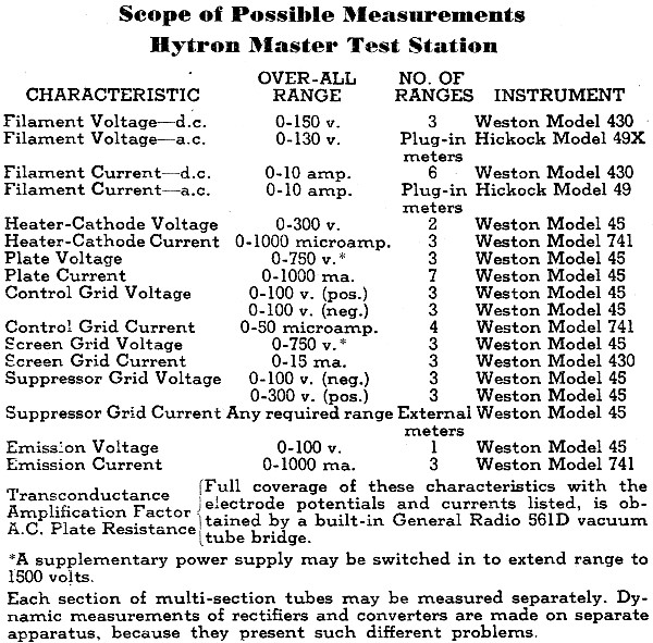
The versatility of this test unit permits highly accurate measurements of the major characteristics of many types of tubes. By Harry G. Burnett Hytron Corporation Dissatisfaction with the limitations of previous kits for production and quality testing of vacuum tubes, led Hytron engineers to design a master test kit which incorporates many features. Flexibility, simplicity of operation, automatic electronic fusing, automatic electronic switching of meter ranges, sufficient power supplies - all voltage-regulated, avoidance of parallax, standardized components, and ease of serviceability were incorporated into the master test station illustrated. The scope of possible measurements is highlighted in the accompanying table. For the sake of simplicity, only the over-all ranges are shown, but the choice of ranges for a given measurement is wide. For example, plate current ranges are as follows: 0-10-20-50-100-200-500-1000 ma. If necessary, external meters can be patched into the circuits for even greater diversity. One of the most interesting features of this deluxe test console is the automatic range control for voltmeters. If the applied potential is increased beyond the range of a given meter scale, a thyratron and associated relay automatically switch in the multiplier for the next higher range. Simultaneously a pilot lamp on the instrument panel lights over the appropriate full scale value engraved on the panel.
Scope of Possible Measurements Hytron Master Test Station *A supplementary power supply may be switched in to extend range to 1500 volts. Each section of multi-section tubes may be measured separately. Dynamic measurements of rectifiers and converters are made on separate apparatus, because they present such different problems. Another novel electronic application is the fuse protection for all current meters except filament current meters (these are conventionally fused). This electronic fuse protection is automatically changed for different ranges. An ingenious circuit permits this same electronic protection even when the range of the measuring instrument is less than the current drawn by the voltmeter itself. A completely shorted tube may be inserted into the test socket without injuring a single instrument. In designing this test station, the engineers incorporated voltage-regulated power packs throughout. The only exception is a 14-volt storage battery (equipped with automatic battery charger) for the lower d.c. filament potentials. The voltages of these regulated packs are essentially constant from zero to maximum, because a separate regulated pack supplies the control tubes. Once the test kit is adjusted for a given type of tube, no readjustments are necessary as different tubes of that type are plugged into the test socket. Two rheostats in the grid circuit of each control tube permit both coarse and fine adjustment of the supply voltage. A glance at the photograph of the test station, discloses the great care taken to avoid parallax in reading the instruments. By placing the meters in a carefully determined arc, and at the proper vertical heights, the eyes of an operator of average height are correctly positioned, assuring greater accuracy in final operation. Painstaking planning provided all controls within easy reach. Accessible drawers are provided for adaptors, spare meters, headphones, and test records. A built-in cathode-ray tube may be used as a visual null indicator for the vacuum tube bridge, instead of headphones. Although not shown in the photograph, an adjustable fluorescent lamp mounted on top of the test station, floods the instrument panel with ample light. The automatic electronic fusing protection for current meters and the automatic ranging of voltmeters make practicable the use of extremely accurate instruments. Use of vacuum tube voltmeters instead of micro ammeters eliminates meter burnouts. The v.t.v.m. is highly degenerated for stability, and adjusted for saturation above the range in use, to protect the measuring instruments from damaging overloads. The accompanying table indicates that meters have been chosen for 1/2 of 1% accuracy. The test station, therefore, may be used as a standard for all other production test equipment. By means of patching cords, any meter or power supply may be connected into any desired tube circuit. Supplementary supplies having ranges of 0-100 volts negative and 0-1500 volts positive, can also be patched into chosen circuits. These features, plus the wide meter ranges, allow full coverage from miniatures to medium-power transmitting tubes. A wealth of controls is furnished for: switching from a.c. to d.c. filament operation; adjusting of transformer primary voltages by transformer taps and by variacs; selecting of proper circuits for heater-cathode voltage measurements; zero adjustment of vacuum tube voltmeters; gain control of the bridge amplifier; switching on and off the voltages applied to the 561D General Radio vacuum tube bridge; switching positive or negative potentials to the grid; and varying the emission voltage between low and high values. It can be readily understood that Hytron's electronic equipment design engineer, Ralph Thompson, and his engineering associates have lavished much thought on this piece of equipment. The assurance of accuracy when the test kit is in operation has repaid them many times for the midnight oil they burned in making their dreams of a really modern and versatile test kit come true.
Posted March 30, 2021 |
||