The G-Line Antenna Lead-In |
||
See also The "G-Line" Community TV System in the November 1956 issue of Radio & Television News. Unique Transmission Line featuring Low Losses over Long Lengths at U.H.F. is Excellent for Fringe Areas. By Leonard Lieberman
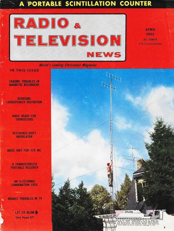
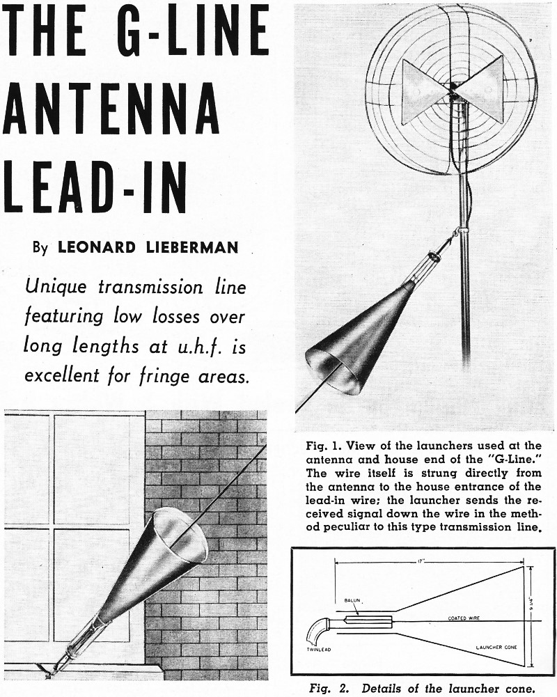
It is well known that a single wire in air which has a voltage impressed on it will radiate energy. This, of course, is basic transmitting antenna theory. Dr. Goubau, in an effort to develop a simple super-high-frequency wave guide, found that when a single wire is coated with a dielectric material, some interesting things occur. The first of these is that the wire becomes nonradiating. As a result, virtually all the energy impressed at one end of the wire is recovered at the other end. The second result noted is that as against the 72-ohm impedance of a coaxial cable of the same size, the impedance of the "G-Line" is approximately 300 ohms. This gives a better match to most antennas which are designed with a 300-ohm output impedance. Another result is that since there is only one wire in the system, as compared to two in the twin-lead lead-in, the wire loss is half that of the twin-lead. A further benefit comes from the fact that just as the wire does not radiate, conversely, it cannot pick up external noises as might come from faulty electric motors, car ignitions, etc. Figure 1 give a view of the launchers used at the antenna and house end of the "G-Line."The wire itself is strung directly from the antenna to the house entrance of the lead-in wire; the launcher sends the received signal down the wire in the method peculiar to this type transmission line. Figure 2 details the launcher cone. To understand why these conditions prevail, let us examine the structure of the unit. If we consider the inner surface of the dielectric coating on the wire as one side of a capacitor and the outer surface as the other side, the amount of radiation would be a function of the leakage current through the dielectric. If the material has a good dielectric constant, this leakage is small and the radiation field is small. It has been found that this field can be kept within one-quarter wavelength from the center conductor. The construction of the line makes it virtually unaffected by rain or layers of soot. In all two-wire systems, these installation bugaboos create low-impedance paths between the two lines. This is true to a greater or lesser extent of all two-wire systems. In the "G-Line," all that occurs is that the dielectric is increased with a very small increase in the loss resulting from additional dielectric currents. This effect is hardly measurable with laboratory-type equipment. To develop the proper wave transmission along the line, special "launchers" are required. These launchers are hollow cones. The large diameter of the cone is determined by the desired size of the field around the wire and by the lowest operating frequency. (It might be noted that these launchers, because of the last-named requirement, also act as high-pass filters aiding the set in the rejection of interfering signals below the u.h.f. band.) The launchers (Fig. 2) are 17 inches long and 914 inches in diameter at the large opening. A nonconducting cone is attached over this opening to keep the launcher weatherproof. The dielectric-covered wire is connected to a "balun" (balance-to-unbalance transformer). This balun has a flat standing-wave ratio over the entire u.h.f. band. The other end of the balun is connected to the short 300-ohm lead from the antenna, or the 300-ohm lead into the building. The loss caused by the two launchers and the two baluns is approximately one db total and is constant over the entire u.h.f. band. The loss in the wire is 1 db per hundred feet. The dry loss in the best of the two-line systems is 1.9 db per hundred feet. Some elementary arithmetic shows that for runs over 125 feet with dry lines, the total loss of the "G-Line" becomes progressively smaller than the loss in the best two-wire system. When the comparison is made with new ribbon line of the type usually used, the "G-Line" is more efficient even for runs as short as 90 feet when dry and 30 feet when wet. These facts indicate the potential of the "G-Line" in fringe reception areas. At u.h.f., one of the limiting factors on the antenna tower height or distance from the house is the loss in the lead-in wire. This loss makes it inadvisable to take advantage of sturdy trees or a hill which might be more than a very short distance away. With the "G-Line," it is possible to run the line from a point 300 to 500 feet from the house without any more loss than would be sustained with 100 feet of currently-used wire. Since the line is made with #14 AWG wire covered with 0.060" of polyethylene, it can be strung for as far as 500 feet without requiring any supports. If it is desired, the line can be supported by nylon string (such as used in fishing line) as long as the wire isn't bent more than 30° at any point. The launchers and wire are connected as shown in Fig. 1. The wire, itself, should be kept at least one foot from the house or the ground. One particular application of this transmission line is in installations where the house is "shadowed" by a hill or obstruction. This line allows the planting of the antenna mast at any convenient high location. "G-Line" is presently being manufactured and marketed by the David Bogen Company, Inc., of New York City, under license from Surface Conduction Inc.
Posted |
||