F-M Receivers and Their Alignment |
||
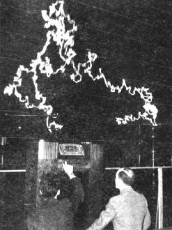
1940 was a big year in the commercial broadcast industry because it was when the FCC began licensing stations for FM operation. Amazingly, that was only four years after Edwin Armstrong first came up with his frequency modulation scheme - fast moving for the government. Simultaneously, equipment manufacturers were cranking out transmitters, receivers, antennas (new frequencies), writing installation and operation guidelines, training servicemen, and doing scores of other vitally important tasks. The advent of FM was considered a very significant technical improvement because of immunity to electrical noise interference. If for no other reason, you should look at this National Radio News magazine article to see the photo of the megavolt artificial lightning discharge created to test and demonstrate FM's tolerance of such phenomena. F-M Receivers and Their Alignment By Joseph KaufmanN. R. I. Director of Education
With about thirty frequency-modulated (f-m) broadcasters in operation and one hundred station permits granted, and with the F.C.C. formally acknowledging that f-m signals will serve public interests, localized radio broadcasting enters a new spectrum, namely 42 to 50 megacycles. Even the most enthusiastic admit that with forty-five million amplitude-modulated (a-m) receivers in use today in these United States, wide public acceptance of f-m will take from five to ten years. At this early date, well-informed receiver merchandisers say that the evils which f-m is said to overcome are not as "wicked" as most people would like to have us believe; hence they argue that f-m may not be the "whirlwind" that initial publicity leads us to believe. However, it cannot be denied that f-m provides an almost noise-free signal, to a degree not attainable with the a-m system. To be sure, local man-made interference has been greatly reduced in our present system, but atmospheric and lightning disturbances still affect a-m receivers. With f-m transmission, however, reception can be noise-free even during local electric storms. Its victory over noise is the greatest appeal, but f-m can provide high fidelity with depths of volume never before considered feasible for a-m. Whether the public as a whole wants true fidelity and natural reproduction is still a highly debatable subject; a great deal of evidence indicates that after years of ear subjugation to false reproduction, broadcasting has developed an ear for reproduction peculiar to radio. How f-m will be accepted by the public, only time will reveal; it is here, however, and offers a real opportunity to trained radio technicians. Review of Fundamentals Before we go on to consider the f-m receiver, a review of the differences between amplitude and frequency modulation deserves consideration. With amplitude modulation, a basic r.f. signal called the carrier is increased and decreased in amplitude, in accordance with the sound intelligence that is to be conveyed. The basic r.f. signal amplitude is never increased more than twice the carrier level, and never reduced to such an extent that an r.f. signal does not exist for an instant. Amplitude modulation produces side frequencies with the highest audio frequency determining the band width. For example, if a 10-kc. audio signal is the limit, modulated on a 1,000-kc. carrier, the side frequencies will extend from 990 kc. to 1,010 kc.
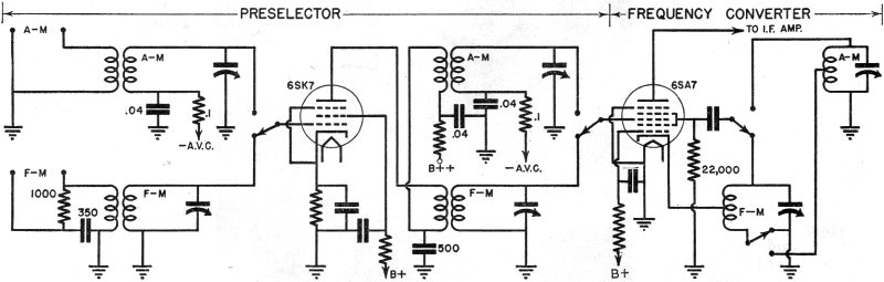
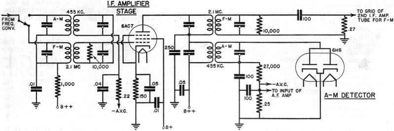
General Electric frequency modulation receiver undergoing comparative listening tests while subjected to million volt lightning discharge. With frequency modulation, the amplitude of the r.f. carrier remains fixed at all points in a given communication system. When no sound is being transmitted, the frequency of the signal is a definite value which is often referred to as the "resting" frequency. This frequency is increased and decreased in accordance with the level (or volume) of the sound being transmitted. Let us look at it this way; sound is the result of condensation and rarefaction of air particles. Condensation results in a dense group of air particles, and rarefaction results in a below-normal amount of air particles. We could arrange to increase the radio frequency for conditions of condensation, and decrease the frequency for rarefaction. There must be a limit to the frequency swing from the resting value, depending on the maximum sound level intended, and this range is referred to as the frequency deviation. Thus, for the loudest sound to be transmitted, the swing could be limited to 75 kc. Since the frequency is varied above and below the resting frequency by this value, the total deviation will then be 150 kc. For example, if the resting frequency is 43,000 kc., for the loudest sound the frequency will swing from 42,925 kc. to 43,075 kc. Should this loudest sound have a 1,000-cycle pitch, the r.f. signal will vary from 43,000 to 42,925 to 43,075 and back to 43,000 kc., one thousand times in a second. If this 1,000-cycle sound has a lower level, the swing could be from 42,995 to 43,005, one thousand times a second. In frequency modulation, the instantaneous frequency corresponds to the sound level at that instant, and the rate at which the frequency is varying above and below the resting value is the pitch of the sound. As far as fidelity of transmission is involved, the deviation can be any value; in fact, equally as good fidelity can be obtained with an overall deviation of 20 kc. as with 150 kc. For maximum elimination of noise. however, a large frequency deviation is desirable. A noise pulse received along with the f-m signal affects the instantaneous amplitude by creating peaks on the r.f. signal, and also affects the instantaneous frequency of the signal. As we will see later. the amplitude peaks of noise are removed by the "limiter" in the f-m radio receiver, but any instantaneous change in the signal frequency will introduce volume pulses after the f-m signal is converted to amplitude changes. If a large frequency change is employed to produce an appreciable change in sound level, the frequency change due to a noise will normally have little effect in producing noise interference. On the other hand, if full range in volume is produced with a small frequency deviation, the frequency change produced by noise pulses will be quite apparent. Essential Stages in an F-M Receiver Once you understand the basic principles involving f-m receivers, you will find these new sets are no more difficult than ordinary sets. As you will shortly see, no radically new circuits are used in a f-m receiver. Conventional vacuum tube circuits, designed to meet special requirements are predominant. The superheterodyne circuit is employed, usually with a stage of r.f. ahead of the frequency converter, and with one or more i.f. stages following the converter. After sufficient amplification has been obtained, a stage which will convert f-m to a-m is required. This modulation converter must be followed by a normal amplitude type of detector. There is, however, a modulation converter which also detects at the same time. The discriminator circuit used in automatic frequency-controlled receivers will produce positive and negative voltages, the instantaneous voltage depending on the deviation in frequency from the reference frequency. Thus, f-m can be converted directly to audio signals by an a.f.c. discriminator circuit. Between the frequency discriminator and the last i.f. stage, a special tube circuit (called the limiter) is introduced. Although its elimination would not prevent f-m reception, its use definitely results in the unique features which make f-m transmission superior to a-m. A limiter removes all amplitude noise pulses, so the discriminator output contains negligible noise signal. The limiter keeps all signal amplitude levels below the permissible swing of the discriminator, thus preventing amplitude distortion. The discriminator also operates so as to favor the desired (stronger) signal and suppress the weaker undesired signal. Finally, the limiter supplies a negative d.c. voltage proportional to carrier intensity, hence it is used as an a.v.c. source. Following the discriminator is a potentiometer which serves as a volume control; its output feeds into a conventional a.f, amplifier and loudspeaker. For high fidelity, both the a.f. amplifier and loudspeaker must be designed to have essentially uniform response over a wide range of audio frequencies. The loudspeaker system usually consists of a low-frequency unit and a high-frequency reproducer, acoustically compensated for high-fidelity reproduction. For some time, f-m receivers will also include circuits for a-m reception. The preselector and oscillator coils for any a-m band will be switched into the circuit; the same switch will also switch in the 42-50 megacycle coils, and in all probability will also introduce the low-capacity variable condensers required for band-spread tuning. Such a combination f-m and a-m circuit is shown in Fig. 1. In each i.f. section of the circuit in Fig. 1, the secondary of the i.f. transformer for a-m (usually about 456 kc.) will be connected in series with the secondary of the f-m i.f. transformer (usually about 1 to 7 megacycles). By connecting the secondaries in series and by preventing any mutual coupling, one i.f. transformer will have negligible impedance at the other frequency, hence its presence will not interfere with amplification of the desired frequency. The primaries of the a-m and f-m i.f. transformers will be switched into the plate circuit of the tube to which they are connected, as shown in Fig. 2. If this is not done, transfer through both transformers would exist, and the selectivity of the circuits would be lost. The i.f. channel for f-m will employ a number of stages, only one of which is shown in Fig. 2. This i.f. channel will feed into a limiter-discriminator type of detector for f-m. The input of the a.f. amplifier will be switched from the f-m detector to the a-m detector according to the type of reception desired. F-M Antenna System. The all-wave antenna used for a-m signals is not designed for high-frequency radio waves. An additional antenna will be desirable. Half-wave antennas are being widely used; these are connected directly to the input terminals of the receiver, and these in turn connect to the primary of the 42-50 mc. antenna coil. Two antennas will thus be normally used for f-m and a-m reception, as shown in Fig. 1.
Fig. 1 - Preselector and frequency converter stages of an a-m and f-m combination receiver. Any of the antennas found acceptable for television reception can be used. Reflection will not be a problem. The horizontal antenna should preferably be faced broadside to the f-m transmitter and adjusted for the least phase cancellation, so the strongest signal possible is accepted. A horizontal di-pole about 11 1/2 feet long will be required. Preselector-Frequency Converter. A stage of amplification preceding the mixer-first detector is to be expected in an f-m receiver in order to over-ride converter noise. The tuning condenser will have a low capacity so the L-C ratio of the tuning circuit will provide high gain. A remote cut-off pentode tube will be used and will be a.v.c.-controlled. Sufficient selectivity must be embodied in the preselector to eliminate image interference and i.f. signal interference.
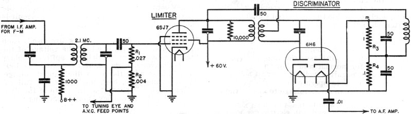
Fig. 2 - Type 6AC7 tube serving as i.f. amplifier tube for both a-m and f-m reception; primary switching is employed. Since the output is through independent a-m and f-m channels, switching is required only at the input of the combined i.f. amplifier and at the input of the a.f. amplifier. A conventional pentagrid converter may be employed in the converter stage. although a triode-pentode tube combination will serve equally well. The local oscillator should be stable, so that the i.f. amplifier and the discriminator characteristics need not be made too broad. F-M Intermediate Amplifiers. These will be of the conventional double-tuned type, carefully designed for optimum coupling so that a resonance curve with a flat top and steep sides will result. As we will see later, perfectly flat tops are not required for strong signals, as the limiter will give the entire r.f. system a flat-top resonance characteristic. However, sufficient broad response will be required so that amplitude distortion does not arise for weak signals. To get sufficient broadness in tuning, either the primary or the secondary of the i.f. transformer will be loaded with a resistance, about 10,000 ohms. Because of loading and the use of a high i.f. value, about 1 to 7 mc., low gain will result and at least two i.f, tubes will normally be required. Limiter. This stage, important as its functions are, is a simple tube circuit. An ordinary pentode tube, operating at low plate and screen grid voltages (about 60 volts) and with no initial grid bias, is used. Grid current flows upon application of an r.f. signal, and this rectified current is made to flow through grid return resistors R1 and R2 as shown in Fig. 3. Using low plate voltage causes the plate current to cut off at low negative grid voltage values. The upper limit of plate current is also kept low by the low plate current, for the space charge readily prevents the flow of electrons to the plate when low accelerating potentials exist; excessive. grid current contributes to low plate current. As a rule, this circuit is designed so that the limiter output does not vary more than 1 volt for all input r.f. voltages above the saturation value.
Fig. 3 - Typical limiter and frequency discriminator circuit. While the limiter circuit prevents excessive rises in the amplitude of the current output, the grid current in the limiter stage causes the operating point to move more negative from the no-signal point shown as a in Fig. 4. The operating point may assume a position such as b, c or d as the input level of the signal increases. The normal operating point will be somewhere between c and d, a condition for high signal input. In such a case, the r.f. signal will undergo half-wave rectification, and plate current will flow for half a cycle or less. Since the plate load of the limiter (Fig. 3) will be a resonant circuit, the voltage developed across the tank circuit will have both alternations of the cycle with the tuning circuit possessing the ability to sustain oscillation at its resonant frequency by virtue of the energy stored in this circuit. If noise pulses make the input r.f. signal swing positive beyond point x in Fig. 4, the pulses will be removed by the saturation effect of this limiter; negative noise peaks will be removed by the cut-off characteristic of the limiter. Of course, this only occurs when a strong signal is received, and the a.f. system is hence designed to load the limiter fully for the weakest signal to be received. If the desired signal fully loads the limiter, causing the operating point to be more negative than point c (see Fig. 4), a weak signal entering the limiter will either cause no plate current variation or will reduce the plate current variation to such a low amplitude that the limiter output resonant circuit will not receive enough energy to sustain this oscillation. It is possible to design the limiter so that a desired signal which has twice the amplitude of an undesired signal, both operating at the same resting frequency, will so completely over-ride the undesired signal that the latter will not be heard. The flow of grid current through grid resistors R1 and R2 in Fig. 3 produces a voltage across the resistors which self-biases the limiter to cut-off or beyond for normal and above-normal signal levels. This negative voltage may, in some receivers, be used to operate an electronic tuning eye,* or to feed an a.v.c. voltage to any of the i.f. or r.f. stages which it may be desirable to control. The resulting a.v.c. action will prevent the limiter from being overloaded too much on very strong signals. In passing through the r.f. amplifier of the f-m receiver, the signal is varying in frequency above and below the resting frequency. If the r.f. system is sharp, as shown by curve 1 in Fig. 5, the signal amplitude will vary from a to b to c to d to e and back to a for one audio cycle. To prevent such extreme variation in amplitude, the frequency deviation would have to be limited so the swing would be from y to z, or the r.f. system would have to be made much broader by loading.
Fig. 4. Limiter characteristic curve.
Fig. 5. How the limiter flattens the r.f. response.
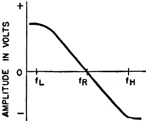
Fig. 6. The S curve of a frequency converter. As was previously, pointed out, the limiter in itself causes the over-all response of the r.f. system to act broad. If the level of the signal is so proportioned that all signal amplitudes above b (amplitude greater than x in Fig. 4) are in the saturation region of the limiter, then all such peaks will be removed. The r.f. amplifier and the limiter together will then have the resonant response portrayed by curve 2 in Fig. 5. The f-m signal may thus embody wide deviation in modulation. The r.f. system is never made too sharp for signals which do not drive the limiter to saturation. Weak signals do not benefit by this action; to receive them with good response, the r.f. and i.f. amplifiers must be reasonably broad. Frequency Discriminator. This circuit does not differ from the circuit used in automatic frequency control. except that it is designed for the i.f. value used in f-m receivers. Such a circuit is shown at the right in Fig. 3. Note that two diode rectifiers are used, each diode being fed with one-half the voltage of the final resonant circuit. Being a split secondary connection, one diode input r.f. voltage is 180° out of phase with the other diode input voltage. At the same time, both diodes get the full r.f. voltage which is present at the plate of the limiter. When the frequency is off the resting value, as it is during transmission of intelligence, the phase relationship between the r.f. voltages acting on each diode varies. As a result one diode gets more r.f. voltage than the other, and the rectified d.c. voltages differ. The difference in d.c. voltage is the f-m demodulated signal; its amplitude is proportional to the amount the signal frequency differs from the resting value and its polarity depends on whether the signal is above or below the resting value. Thus, while the f-m signal is varying in frequency due to modulation, the net d.c, voltage across R3 and R4 in Fig. 3 is changing in amplitude, with point m becoming alternately positive and negative with respect to ground. Condenser across R3 and R4 remove all r.f. components. The discriminator must be designed so that increases and decreases in frequency from the resting value produce proportional changes in d.c. output voltage, as shown in Fig. 6. This linearity must extend for the full deviation in frequency. It is important to standardize on the maximum deviation that will be used, and design the discriminator accordingly. In fact, the discriminator should be able to handle even a greater deviation, to take care of the normal drift in the frequency of the receiver oscillator. By designing the discriminator for wide frequency deviation, this stage will function for f-m signals with low frequency deviation. A discriminator designed for a narrow frequency deviation would distort when an f-m signal with a wide deviation was received. Alignment of F-M Receivers Alignment of an f-m receiver will differ somewhat from the procedures used for a-m receivers. It may surprise you to learn, however, that this alignment can be done with standard servicing equipment having suitable ranges. First, the discriminator will be lined up, A high-resistance d.c. voltmeter, preferably a vacuum tube voltmeter, is connected across one diode load resistor. To introduce a signal, connect the service signal generator to the grid-chassis of the limiter tube. The signal generator should be set exactly to the i.f. value for f-m, and its output should be as high as possible, about 1 volt. Adjust the primary of the discriminator transformer for maximum output. Now connect the d.c, voltmeter across both diode loads, and adjust the secondary of the discriminator transformer for zero output voltage. To align the resonant circuit ahead of the limiter stage, connect the signal generator (still set at the i.f. value for f-m ) to the grid-chassis of the stage ahead of the limiter. A 0 to 100 micro-ampere meter can be connected in the grid return of the limiter, or a high-resistance voltmeter (or v.t.v.m.) can be connected across the grid return resistor which produces the a.v.c. voltage. Adjust the resonant circuit ahead of the limiter for maximum deflection. When a peak reading is obtained, the output reading should be high enough to indicate that the limiter is being saturated. To do this, the signal generator output should be set up to a high output value. This can be checked by noting the output across one diode load in the discriminator; increased input to the limiter should show little rise in output voltage. This condition is essential, for it is necessary to have the same loading of the limiter on the resonant circuit as would exist in normal operation. This loading affects the response of the resonant circuit. If you align this circuit with little load, a different peak setting will result. Advancing the signal generator one stage at a time aligns each resonant circuit for maximum limiter grid current or self-rectified d.c. voltage. The i.f. channel for f-m will be aligned when the signal generator is connected to the input of the mixer-first detector, Next is the alignment of the preselector and oscillator. For this adjustment, the signal generator is connected to the two antenna posts. The oscillator is always aligned first, and the preselector is adjusted for maximum grid current or voltage in the limiter. Alignment will, of course, depend upon the type of tracking employed. One method worth mentioning involves the iron-core coil in the oscillator. The signal generator and the receiver dial are set at a low frequency (about 42 to 43 mc.), and the oscillator core aligner is adjusted for maximum output. Then the signal generator and receiver are set to a high frequency (about 49 to 50 mc.) and the trimmer shunting the oscillator variable condenser is adjusted for maximum output.
* An f-m receiver should be tuned for least noise, not for maximum sound level. An electric eye working on peak limiter grid current offers an excellent tuning indicator.
Posted March 3, 2022 |
||