Crystal Diodes in Modern Electronics |
||
Use of the word "modern" in titles of books or magazine articles has always bothered me because of how quickly the referenced topic becomes obsolete. It is only "modern" for a relatively short period of time. In 1951 when this article appeared in Radio & Television News magazine, germanium was the dominant semiconductor in use for diodes and transistors. They could be used in small signal circuits of up to about 500 MHz. That meant they could easily replace vacuum tubes in AM and FM radios, and at least the IF and baseband sections of TVs. You might think that would have represented a big component cost savings, but semiconductors were much more expensive than vacuum tubes at the time. Still, the power savings, size reduction, and higher reliability made the circuit changes worthwhile. Doing so also helped foster consumer acceptance of the newfangled technology. You will note the reference to "crystal diodes," aka "crystal rectifiers," which led to the still oft used "CR#" designation for diodes on schematics (although "D#" has become more common). This is the second of a three-part series on crystal diodes, by David Armstrong. I have the other two parts, but for some reason scanned this one first. The other will be added later. Crystal Diodes in Modern Electronics
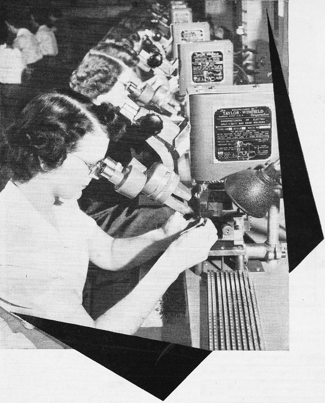
Bank of whisker machines at G-E's germanium products plant in Clyde, N. Y. Operators use microscopes during welding process. Machines form and weld .003" dia. whiskers to pin and lead assemblies of diodes. By David T. Armstrong Part 2. A review of the various uses of germanium crystal diodes in power and rectifier applications. The applications of germanium diodes, shown in the accompanying circuits, are believed to be of general interest. While they are not the only actual uses, they are indicative of the variety of possible applications. Each crystal type presents its own special requirements which determine circuit design as well as values of associated condensers, resistors, and coils. Large Variety of Possible Uses In order to capture the interest and stimulate the imagination of a large number of readers the applications of germanium diodes are covered here in the following groups: power and rectifier supplies, AM (broadcast) receivers, FM receivers, television, amateur, instruments, and miscellaneous applications. This will make a relatively complete discussion of general applications of germanium diodes to modern electronics, and it seems desirable to cover the material in this way so that reference may be made to previous sections as the series of articles progresses. The circuit diagrams will be as complete as it is possible to make them, and, wherever practical, maximum and minimum limits will be indicated, for voltage and current limitations determine the success or failure of the diode crystal in a given circuit. In general, maximum frequency limitations on diodes do not apply since the upper frequency limit of 100 mc. for germanium crystals is well within the frequencies encountered beyond the front end, even with the new 44 mc. i.f. Diodes perform well at AM and FM i.f., but they contribute the least noise to a circuit above 30 mc. On the basis of much experimental work germanium diodes are believed to be useful up to frequencies as high as 500 mc. Rectifier Applications
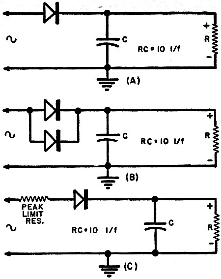
Fig. 1 - Series diode rectifiers used in low impedance circuits. (A) Circuit useful over a range of frequencies from d.c. to 100 mc. (B) Method of increasing current in a series diode rectifier. The crystal can be of any type. (C) Peak limiting resistor acts as protection for the crystal.
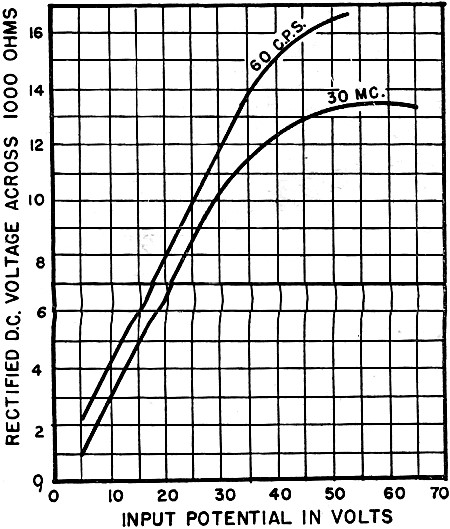
Fig. 2 - Comparison of the performance of a crystal diode at 60 cps and at 30 mc. Over the voltage range at which most crystals operate, the curves are, to all intents and purposes, linear and parallel. The circuits in Fig. 1 are variations of low impedance series diode rectifiers. These are general circuits applicable to power frequencies, as well as the radio frequencies encountered in AM, FM, and TV. These are substantially the same circuits that would be used with tube type diode rectifiers. All the circuits in A, B, and C of Fig. 1 are low impedance load circuits. With a 1NS6 type high conductance diode these low impedance circuits are useful up to 40 volts peak and are capable of delivering at least 30 ma. short-circuit current to the load at 2 volts rms applied. By virtue of its exceptionally low dynamic impedance a 1NS6 will provide high current efficiency with load impedances of 1000 ohms or less. In B is shown parallel operation of two or more crystals to permit greater currents to be handled, or to increase the current delivered to the load at low input voltage levels. Whenever possible, use a germanium diode to operate into very low impedance loads because they are well suited for such circuitry by virtue of their extremely low forward resistance. The 1NS6 has an average forward resistance of less than 60 ohms with +1 volt applied across its terminals. This enables it to pass comparatively large currents with relatively low signal voltages and gives it ideal characteristics for driving low impedance networks. Fig. 3A shows a rectifier application for high impedance loads. Consider a load impedance of 0.5 megohm or greater. Because the reverse dynamic impedance of the 1NS4 reaches a maximum of over 2 megohms at approximately -10 volts (see Fig. 3 in Part 1 of this series), this circuit will function exceptionally well with input levels on the order of 20 volts rms. The effects of diode reverse conductance upon the efficiency of rectification are substantially reduced by designing the circuit with two high reverse resistance type crystals, like the 1NS4, in series. The 1NS4 has unusually high reverse resistance and it is a useful element in circuits involving high values of load resistance. The magnitude of the reverse resistance will vary with the amount of voltage impressed across the diode. Therefore, for proper use of crystals it is important to keep these two considerations in mind: 1. What is the average signal level at which the diode will be called upon to work? 2. What is the approximate resistance value of a given diode for this average signal level region? Thus, the higher the value of the load resistance in ordinary circuits of a series type, the more important it is to use a germanium diode with high reverse resistance, and to use it where its reverse resistance is maximal. When operating with low signal level into high impedance networks it is extremely important to increase the signal level to that voltage which will permit use of the diode at the point where the reverse resistance is at a maximum. The resistance of most germanium diodes increases rapidly as back voltage is increased from zero to -10 volts; for the 1N54 the resistance at -10 volts is approximately 2 to 2.5 megohms. For high signal levels on the order of 20 volts rms or more, it is desirable to design a circuit with the diodes in series, as shown in Fig. 3A. By splitting the signal voltage the diodes present their maximum resistance to the circuit. Because they are in series the resistances are additive. This produces a composite back resistance which is relatively high, even for loads in the megohm range. Keep in mind that the forward resistance will be increased somewhat, but this will have no appreciable effect because of the high value of the load resistance. Fig. 3B shows a high voltage level rectifier which is a basic circuit for all crystal types. In applications with a meter for a.c. measurements up to 1000 volts 1N34 or 1N48 type crystals are generally used in this series shunt arrangement. Note that the peak inverse voltage is removed from the series rectifier. The 20,000 ohm series input limiting resistor acts in conjunction with the shunt crystal to clip the inverse half of the cycle. This permits the application of input voltages of peak value up to several times the rating of the crystal and provides a useful circuit in which a wide range of input voltages may be accommodated. The shunt resistor may be eliminated in meter applications.
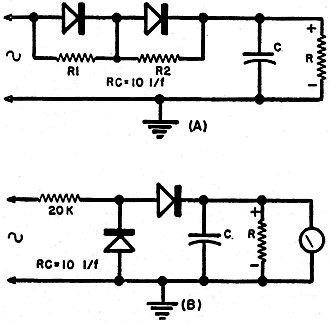
Fig. 3 - (A) High impedance series diode rectifier circuit. Use of resistors about equal in value to back resistance of the diodes insures nearly equal voltage distribution between diodes. (B) A high voltage rectifier circuit using any type diode.
Fig. 4 - (A and B) Basic shunt diode rectifier or clipper circuits. (C) Shunt diode rectifier circuit which may be used with any type of crystal. The capacity of C depends on frequency and permissible current surge through the crystal employed. R is the shunt load resistor. (D) Shunt diode rectifier and filter circuit which may be used with any type of crystal. The Type 1N60 and 1N64 are better suited for high frequency i.f. detection than general purpose types such as the 1N34 or 1N48. Fig. 3. (A) High impedance series diode rectifier circuit. Use of resistors about equal in value to back resistance of the diodes insures nearly equal voltage distribution between diodes. (B) A high voltage rectifier circuit using any type diode. A shunt diode rectifier circuit is shown in Fig. 4. This is also a basic clipper circuit. For convenience and comparison both tube and crystal are shown. These circuits function extremely well at frequencies from d.c. up to 100 mc. Recent investigations into the matter have revealed data which indicate that germanium diode crystals will be useful up to frequencies of 500 mc. The condenser C1 in Fig. 4C prevents d.c. feedback and the resistor R is the shunt load resistor. Note that in these circuits the cathode is connected to the positive d.c. terminal output. Fig. 2 shows a comparative set of curves for a crystal diode at 60 cps and 30 mc. Over the voltage range at which most crystals operate the curves are for the most part linear and parallel. Bias Applications A crystal diode will supply from -1 to -3 volts of bias, and makes an excellent fixed bias supply for a class A audio amplifier. Fig. 5A shows a simple and typical low voltage bias supply taken from the 6.3 volt secondary of a power transformer. The 1N34 or 1N48 performs the function of a rectifying crystal and the condenser input filter smooths out a.c. ripple in the d.c. output. Negative bias is taken from the lead connected to the anode of the crystal, while the cathode is grounded through the transformer secondary . Note again that the cathode is the positive d.c. output terminal. This is a simple half-wave circuit and much more economical than the one shown in Fig. 5B, but it is not quite as good. It would be hard to beat the circuit in Fig. 5B for fixed bias that will be satisfactory and trouble free. This circuit is a bridge type fixed bias supply which will supply about -3 volts of negative bias. The negative d.c. output, you will note, has the anodes in parallel. For this type circuit a germanium quad (or varistor) of the octal socket type may be used because it will make a compact assembly involving a minimum of circuit connections, but such a component would be more expensive than four 1N34 or 1N48 crystals. The filter resistor, R1, is 1000 ohms and, since the current drain in a bias supply is negligible, a 1/2 watt size is ample. The value of the load resistor R2 is determined by the negative output voltage desired. As the value of R2 increases the output voltage increases. At 1000 ohms approximately 3 volts of negative output bias voltage is available. The d.c. negative output may be varied from about -1 to -3 volts by using a potentiometer in place of the shunt load resistor; the suggested potentiometer is shown on the diagram as a dotted line. The arm varies the amount of negative bias in the circuit.
Fig. 5 - (A) A simple fixed bias circuit using either a 1N34 or a 1N4S. (B) a bridge type fixed bias supply using same crystals. (C) A simplified bridge type bias supply which utilizes 1N34's or 1N4S's. This is a less expensive variation of the standard bridge type bias supply of (B).
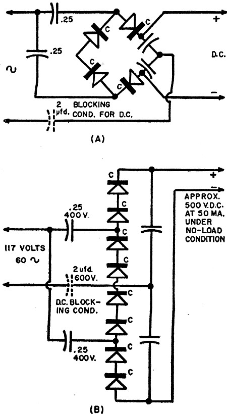
Fig. 6 - (a) A simplified voltage quadrupler which uses either a 1N34 or a 1N48. Value of the condensers depends on frequency at which quadrupler is operated. (B) An improved version of quadrupler shown in (A). Diodes may be either 1N34's or 1N4S's. Two diodes in series in each leg are desirable in order to withstand peak inverse voltages present in circuit. Fig. 5C shows a simplified bridge type circuit. It is better than the one shown in Fig. 5A, and less expensive than the one shown in Fig. 5B. Voltage Multipliers All types of circuits possible with vacuum tubes or selenium rectifiers may be used with crystal rectifiers providing suitable modification of the other circuit components is made to permit the use of the crystals within their rated values. Fig. 7 shows a half-wave and a full-wave voltage doubler which may use either Sylvania type 1N34 or G-E type 1N48 crystals. One of the chief values of these circuits is that they may be used at a variety of frequencies, from the power line frequency through the audio frequencies, and on up into the radio frequency ranges. From 60 to 10 kc. it is suggested that the values of the condensers be approximately 8 μfd.; from 10 kc. to 10 mc. something like 0.25 to 0.02 would be satisfactory; and above 10 mc., 1000 μμfd. down to 47 μμfd. is suggested. A doubler circuit will deliver about twice the input volts at low output current drain.
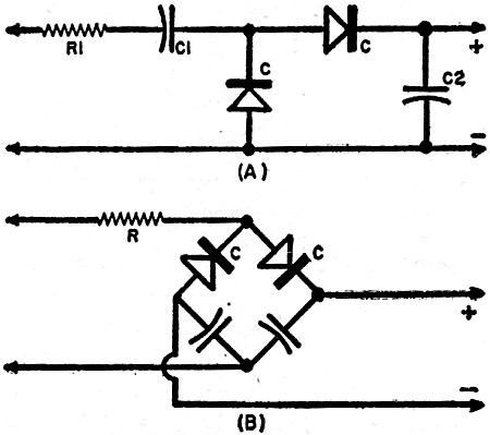
Fig. 7 - (A) Half-wave doubler circuit using a 1N34 or 1N4S. R1 is a peak limiting resistor. The values of C1 and C2 depend on frequency at which voltage is to be doubled. Although this is a conventional power supply rectifier application, it may be used for other general or special purposes. (B) A full-wave doubler, modified bridge circuit using 1N34's or 1N48's. R is the peak limiting resistor. Capacity of condensers may vary from 10 μfd. at 60 cps to 47 μμfd for 44 mc. i.f. use. Fig. 7B shows a full-wave doubler in a modified bridge circuit. This contains the same components as the half-wave doubler shown in Fig. 7 A but they are arranged to perform their functions in a simplified bridge circuit. This will deliver full-wave voltage at about twice the input a.c. for low load current drains. It is important to design any diode circuit so that the load current drain will not exceed the maximum limit indicated by the characteristics of the diode used. In power rectifier circuits, it is extremely important to stay within the peak inverse voltage rating, even more than within the maximum current rating. When germanium diodes are subject to continuous voltage overrating they literally explode. No one would appreciate having this happen. Fig. 6A shows a simplified voltage quadrupler. Observe the similarity of such a circuit to what one finds when using seleniums. But note also the polarity connections to the anode whisker and the cathode germanium slab. This quadrupler circuit will provide approximately 500 volts of d.c. from the typical 115 volt, 60 cycle a.c. input supply, or about four times the input voltage. The maximum current that may be drawn is about 40 ma., depending upon the diode crystal used. In Fig. 6B note that each of the four legs of this quadrupler system works better with two diodes series-connected in order that the crystals may withstand the peak inverse voltage impressed upon the components. The G-E type 1N48 and the Sylvania type 1N34 will perform quite satisfactorily in this circuit. The condensers should have a value of 0.25 μfd. and be rated from 400 to 600 volts; 400 volts may do the trick in many cases, but the safety factor with 600 volts is much better. Note the addition of the blocking condenser rated at 2 μfd., 600 to 1000 volts, to prevent d.c. feedback through the line. If two quadruplers are connected in series it is possible to obtain 1000 volts, but this approaches the fantastic. There are simpler and less expensive methods of achieving 1000 volts of d.c. at 50 ma. Rectification and Frequency Rectification efficiency decreases with an increase in frequency and a crystal with a large capacitance shows a greater and faster drop in rectification efficiency than a crystal with a small capacity. In general the lower the contact capacitance the better the high frequency performance of the crystal. Therefore a crystal which performs well at low frequency will perform well or better at a higher frequency, up to the limit of 100 to 500 mc. Crystals with very high back resistance usually perform best at low frequencies. However, the mobility of electrons in such a crystal is low at high frequencies. Therefore, rectification efficiency is increased at high frequency by doping the germanium and lowering the back resistance. These crystals are then relatively poor at low frequencies. (To be continued)
Posted September 23, 2020 |
||